


Photo Import
Photo Import
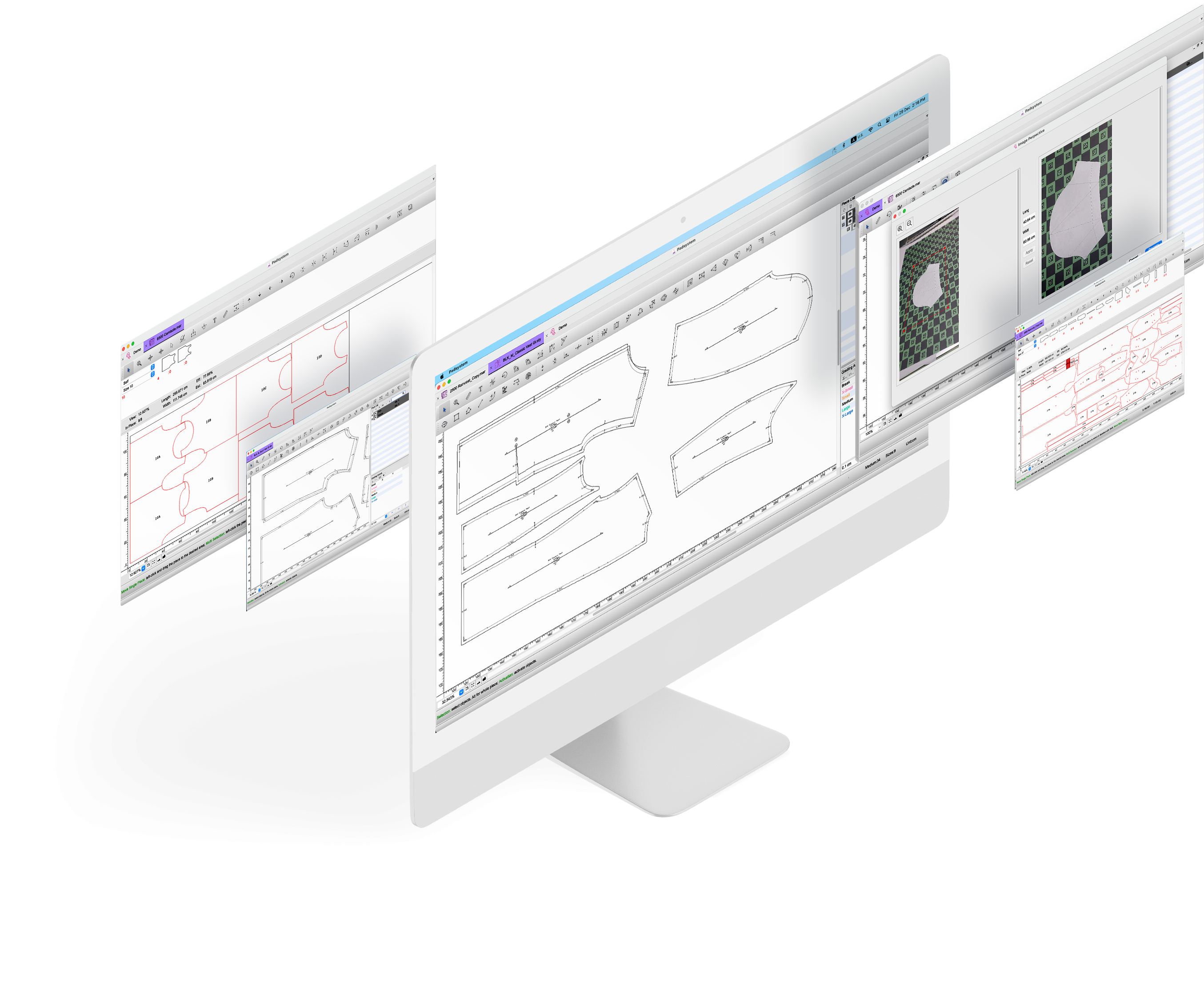
Padsystem 8.0 now available to Photo input and create a digital conversion file within Padsystem Cloud.
Padsystem Cloud
Padsystem Cloud
The cloud platform has been completely revamped with new features to increase ease of use.

Multiple File Open
Multiple File Open
Users can now regulate licence usage via the “members” option. Invited guests can be given rights to allow them to make use of your licence (limited to your store only).
New License Grade
Different License Grade is now Launched!!

- Education

- Standard
Our Partners
