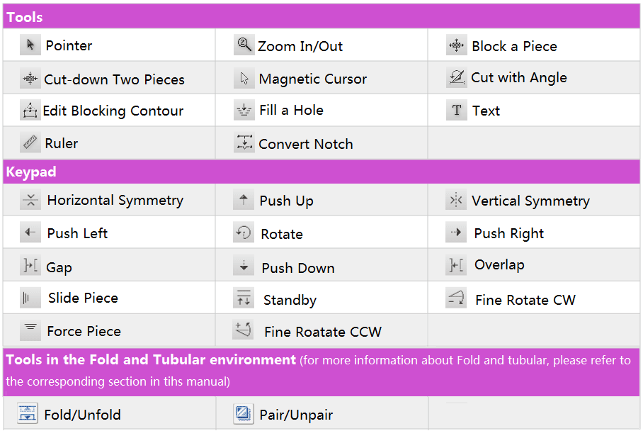
The following picture shows the tools and keypad of PAD System™ Marker Design for nesting. User can place or manipulate the pieces by using the tools and the keypad, to achieve the desired result.
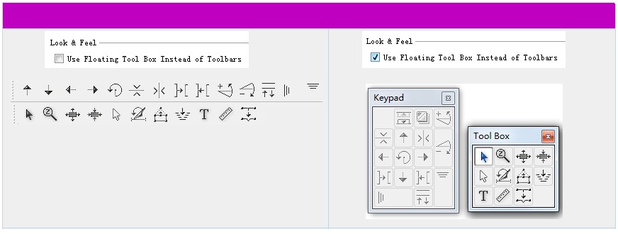
User can go to [Options]-[Preferences]-[Comapatibility] to select the desired way the tools display. Select “Use Floating Tool Box Instead of Toolbars”, then it shows toolbox; uncheck it to show toolbar.
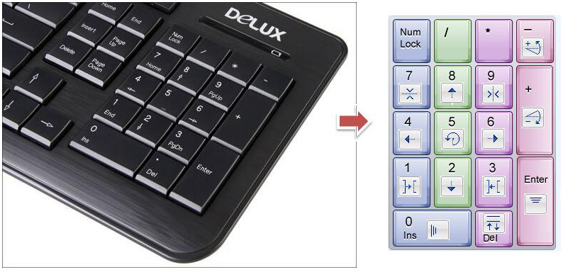
The corresponding keys on the keyboard of the tools:
Function of the Tools
 Pointer
Select or move pieces.
Place pieces to simulation area
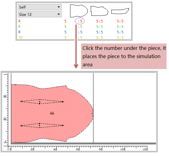
Place one by one:
Select the tool, click the number under the pieces in the Chart area, the piece is placed to the simulation area:
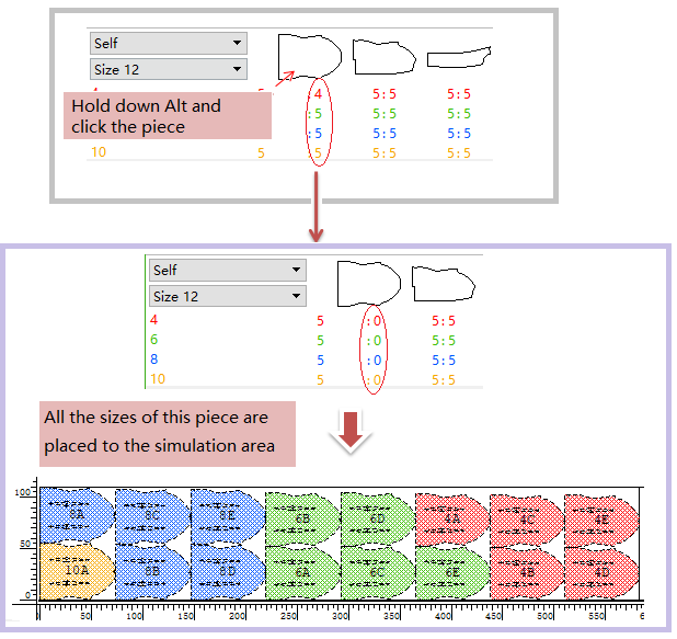
Place all sizes of the chosen piece
Hold down Alt (Windows) or Option (Mac) or Alt+Windows (Linux) key, and click the piece in the Chart area, the all sizes of the chosen piece are placed to the simulation area:
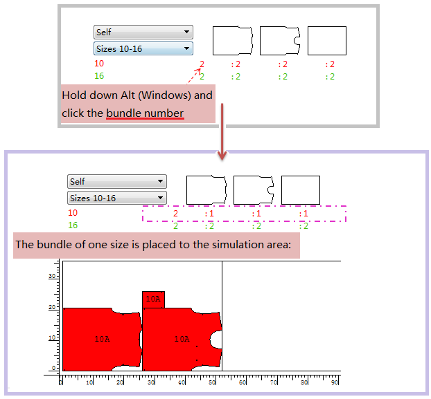
Place a set of piece:
Hold down Alt (Windows) or Option (Mac) or Alt+Windows (Linux) key, click the number representing the sets, and the set of pieces is placed to the simulation area:
備註
Click once for one set,and click twice for two sets.....click the number till all sets are placed.
Select the piece
Select a single piece:
Select Pointer tool, click the piece. The contour of the piece becames dotted line, which means that the piece is selected.
Select more pieces with Shift key.
Move the pieces:
Move a single piece:
Select Pointer tool, click the piece without releasing the mouse button, drag it to desired location.
Move multiple pieces:
Select Pointer tool, click the group of pieces without releasing the mouse button, drag them to desired location.
備註
Get more information from the section [Treatment]-[Group] of this manual.
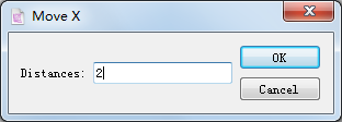
Move piece horizontally by inputting precise value:
Select the Pointer tool, and select the desired piece (select more pieces with Shift key). Then hold down Ctrl+Alt (Windows) or Command+Option (Mac) key, and click Pointer tool in the tool box. A dialog box appears, enter the desired value, click OK to finish operation.
Quick move:
Double-click the piece without releasing the mouse button, drag it to desired location.
 Zoom In/Out
Enlarge or reduce the view of working area. The range is from 0.5% to 2000%.
Zoom In
Select the tool
Zoom Out
Hold down Alt (Windows/Linux) or Option (Mac) key, “-” appears in the center of the glass, then click the desired area (or drag out a rectangle to enbrace the area).
To Zoom In/ Out by Mouse Wheel
Hold down Space bar key and move up/down the mouse wheel to enlarge/reduce the view.
 Block a Piece
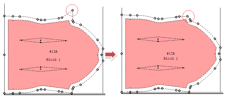
Allow user to create a blocking allowance around a pattern piece (or a group of pieces).
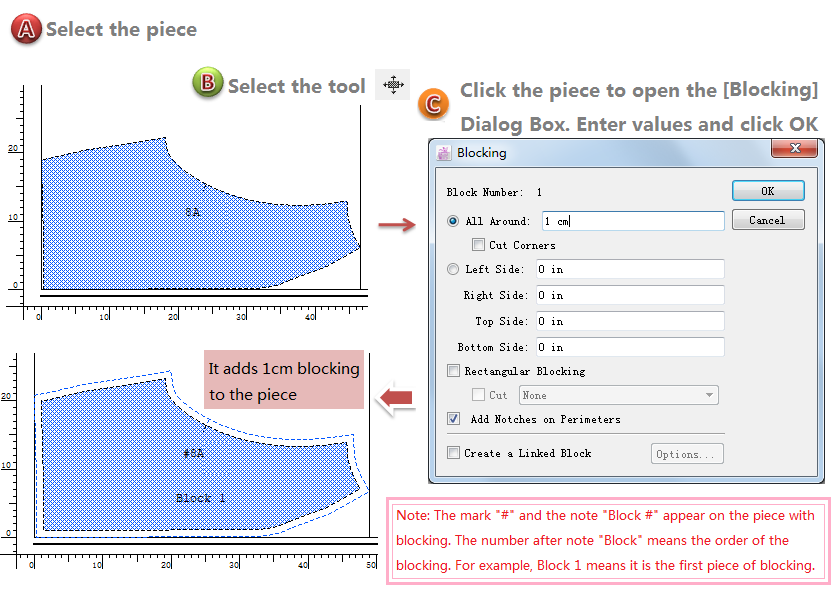
Block a piece
- Select a piece;
- Select the
- Click the piece, the Blocking dialog box opens;
- Enter the blocking allowance in the appropriate text box and select the desired options and click the OK button.
備註
The “Block X” only appears after blocking pieces individually in the simulation area.
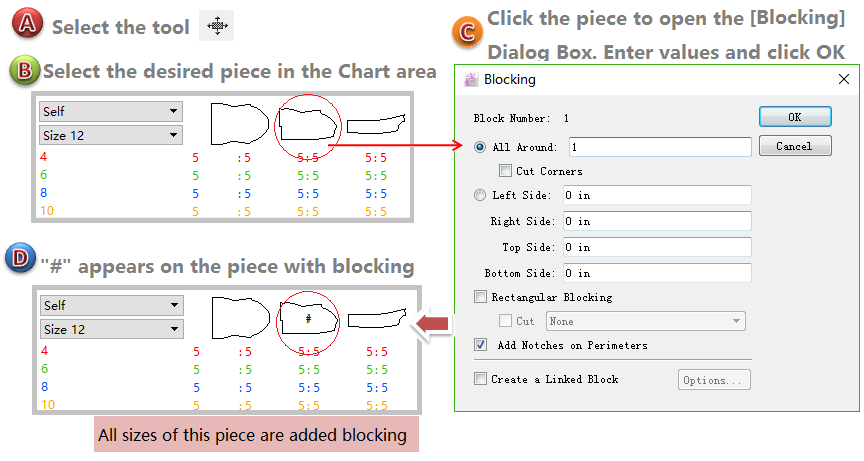
Create a block on multiple sizes
- Select the
- Click the piece in the Chart that you wish to block to open the Blocking dialog box;
- Enter the blocking allowance in the appropriate text box and select the desired options, and click the OK button;
- “#” marks on the piece after finishing creating blocking.
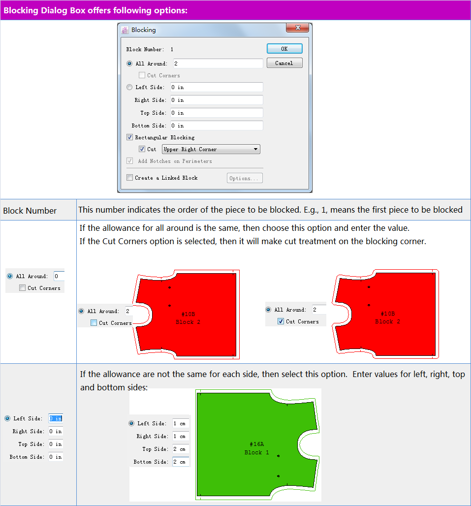
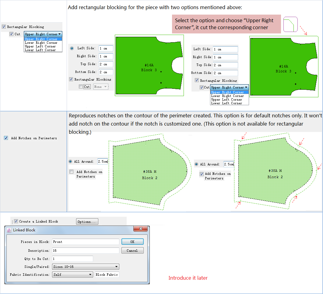
Introduction of the options in the Blocking dialog box
Create a Linked Block:
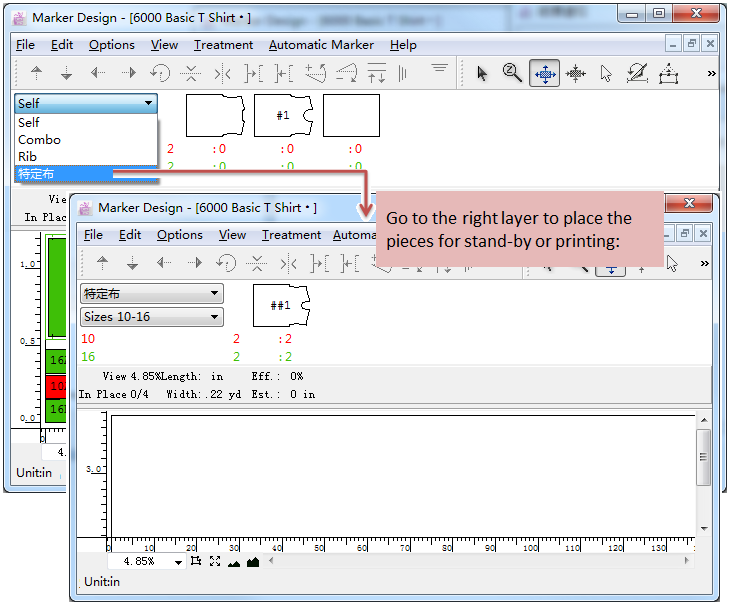
Check this option when create a block, the system will generate the linked fabric according to the settings in the same layer, and it named the linked fabric as “Block Fabric” by default. So the pieces will be collected in the original fabric and the corresponding linked fabric. User can go to the desired fabric to place the blocked fabric.
For example:
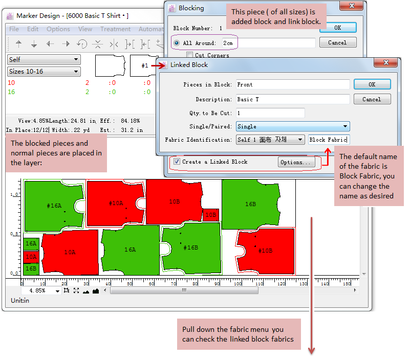
備註
During creating multiple blocked pieces, if the name enter for the linked block fabric is different, then the pieces will be placed under the different linked fabric.
Edit or remove a block
-Edit a block:
- Select the
- Click the block;
- The Blocking dialog box opens, enter your modifications in the Blocking dialog box, click the OK button.
-Remove a block:
- Select the
- Click the block;
- The Blocking dialog box opens, edit the block by changing the All around value to zero (0), click the OK button.
 Cut Down Two Pieces
The Cut-Down Two Pieces tool superimposes two pattern pieces in the Fabric Simulation Area for a cut-down.
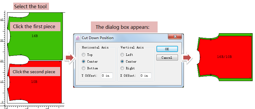
Superimpose two pieces for a cut-down
- Select the
- Click the first piece in the Fabric Simulation Area, and then click the second one.
- It opens the Cut-Down Position dialog box, select the desired options and click OK button;
- The pieces are superimposed and considered as one.
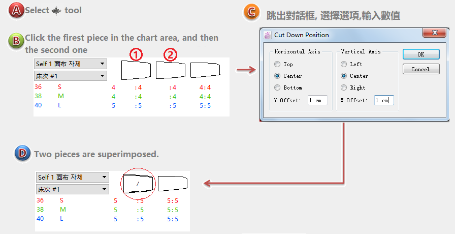
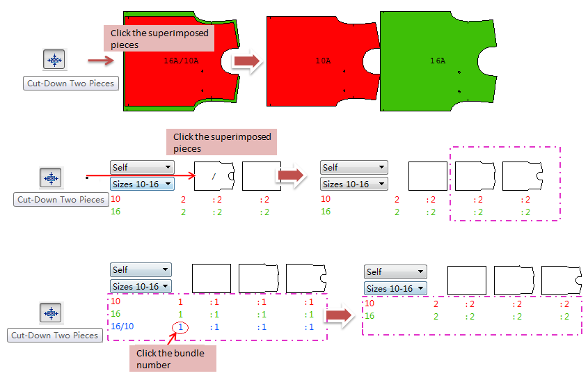
Cut-Down two pieces in the Chart area
- Select the
- Click the first piece in the Chart, and then click the second piece;
- The Cut-Down Position dialog box opens,enter the desired positioning, click the OK button.
- It applies on all the sizes of two selected pieces. When you place the cut-down piece to simulation area, they are superimposed according to the settings.
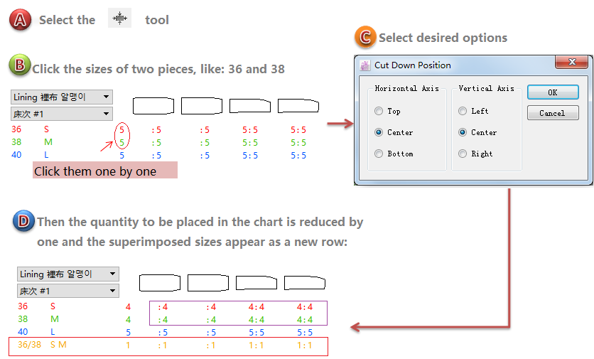
Cut-Down two sizes in the Chart
- Select the
- Click the first breakdown and then the second one;
- The Cut-Down Position dialog box opens, enter the desired positioning, and click the OK button;
- When cut-down is done, the quantity to be placed in the chart is reduced by one and the superimposed sizes appear as a new row.
How to cancle cut-down
Select
 Magnetic Cursor
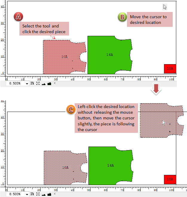
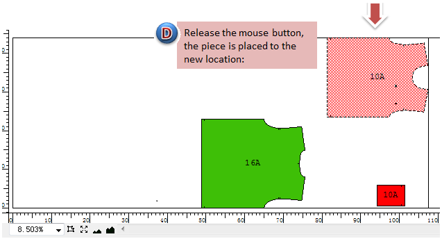
The Magnetic Cursor tool attaches a selected piece to the cursor. This function can easily retrieve pieces that have been brought down outside the screen visible area.
- Select the Magnetic Cursor tool;
- Click once on the desired piece;
- Click the desired location in the Fabric Simulation Area without releasing the mouse button, and move slightly, the piece follows the cursor, then release the mouse button
 Cut with Angle
The Cut with Angle tool enables you to cut a pattern piece freehand and add a seam allowance.
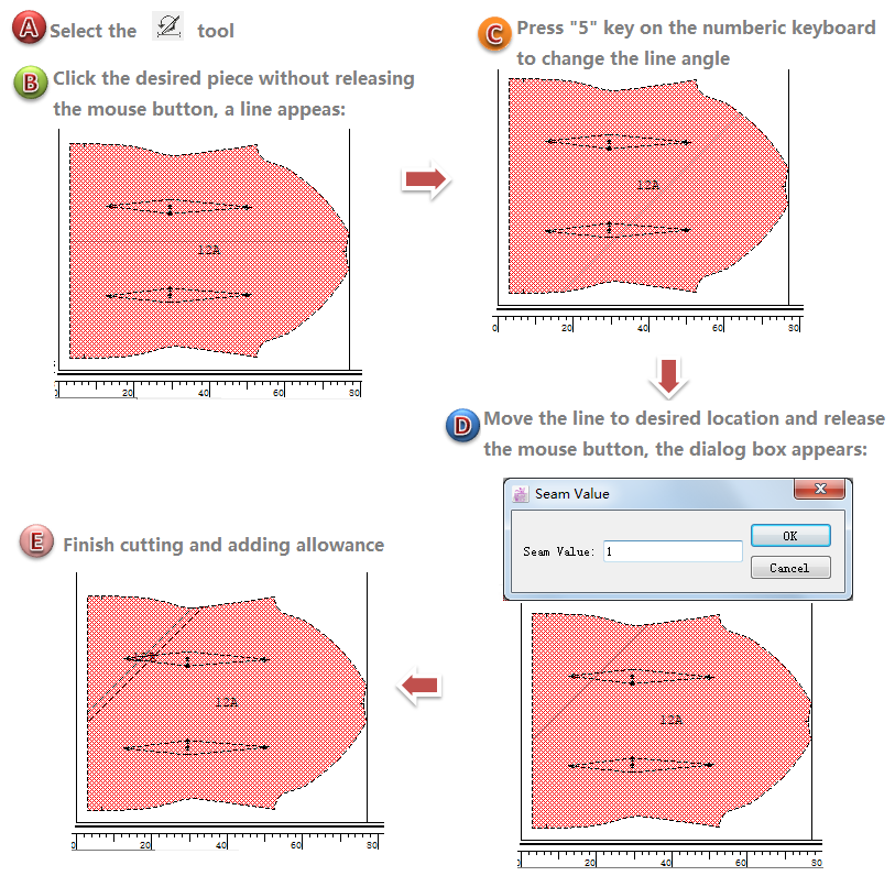
Cut a piece freehand and add a seam allowance
- Select the
- Click the piece and hold down the mouse button. A horizontal line appears;
- To shift the angle of the line, press the 5 key on the numeric keypad on the keyboard until the desired angle is reached;
- Release the mouse button. The Seam Value dialog box opens;
#.Enter the Seam value. Click the OK button.
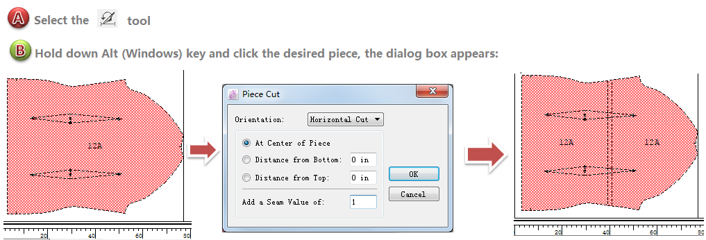
Set the horizontal or vertical position of the cutting line
- Select
- Hold down Alt (Windows) or Option (Mac) or Alt+Windows (Linux) key, and click the desired piece, the [Piece Cut] dialog box appears ;
- Select the orientation of your cut (Horizontal or Vertical), the seam value, select the proper radio button for the seam positioning, then click the OK button.
 Modify Blocking Contour
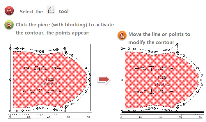
Edit Blocking Contour enables you to modify the existing contour of a blocking allowance by moving existing points, adding new points to the shape or removing points from it.
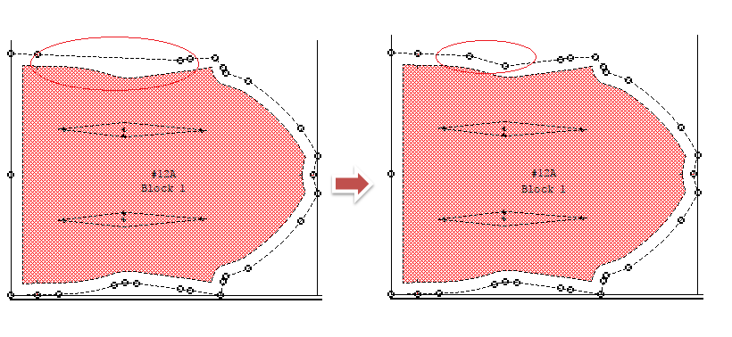
Modify the contour by moving existing points/segments
- Select the
- Click once the blocking. It activates the shape and show all points;
- Select the points or segment to be modified, hold down the mouse and drag it to its new location.
Add new points
- Select the
- Click once the blocking. It activates the shape and show all points;
- Click the new point location on the blocking allowance contour.
Remove points
- Select the
- Click once the blocking. It activates the shape and show all points;
- Hold down Alt (Windows) or Option (Mac) or Alt+Windows (Linux), click on the point you wish to remove.
 Fill a Hole
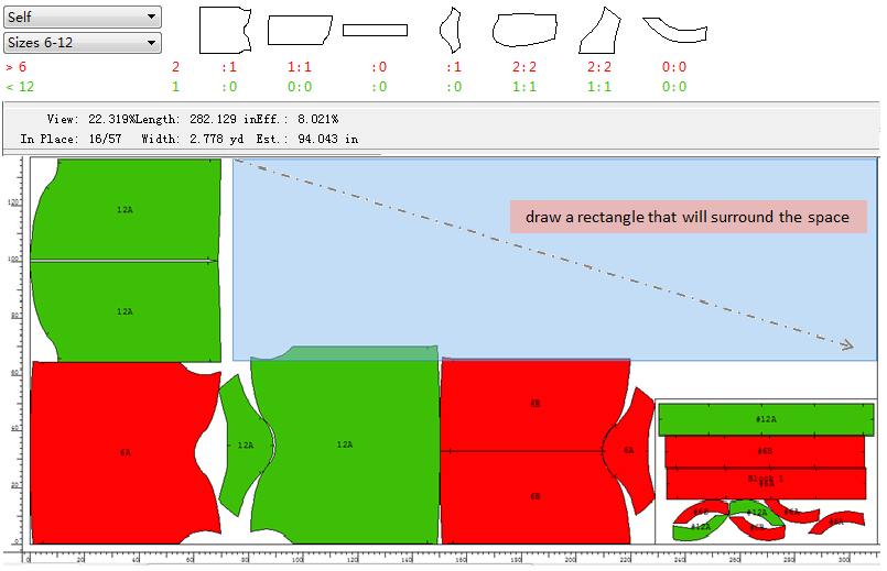
It enables the system to evaluate the hole and place the largest pieces left in the Chart available to fill the space.
How to do:
- Select the Fill a Hole tool;
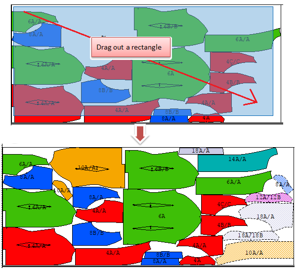
- Click once, hold down the mouse button and drag to draw a rectangle that will surround the hole. Release the mouse button;
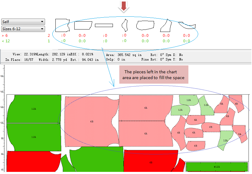
- It places the pieces left in the Chart to fill the space.
- Example 1:
Example 2:
 Text
Text
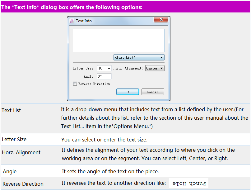
The Text tool enables you to write notes on the standby area or simulation area, or edit the existing notes.
Input new text
Add text on the standby or simulation area.
- Select the
- Click the desired text location, the dialog box appears;
- Input the text in the dialog box and select the desired options, then click [OK] button.
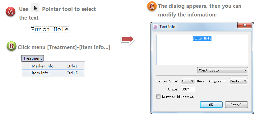
Edit the existing text
- Select the
- Select [Item Info…] in the [Treatment] menu. The Text Info dialog box appears, allowing you to change the text;
- Edit the text and then click [OK] button.
 Ruler
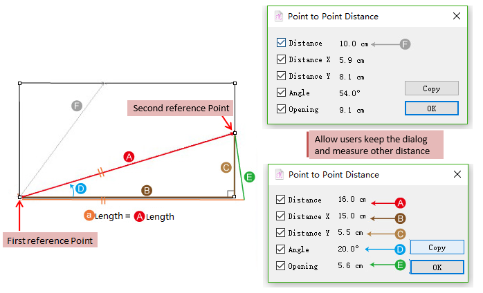
The Ruler tool allows you to measure the distance between any two points.
- Select the
- Click the first reference point, and then the second one, the dialog box appears;
- The distance informations are shown in the dialog box and they are available to be copied.
The [Copy] button allow users to copy the values in the dialog box and paste these values into Notepad or another word processing application.
Users can keep the dialogs open and take measure on another piece. Two dialogs appear and allow users to compare the measurement.
 Convert Notch
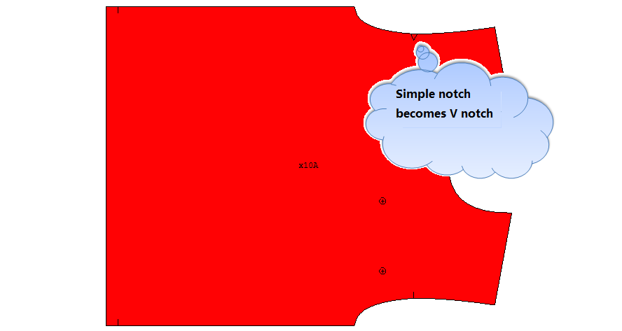
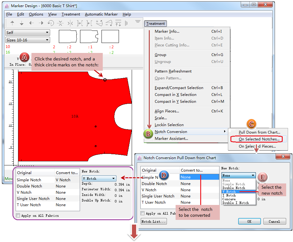
The Convert Notch tool enables you to convert one or more notches on pieces that have already been placed in the Fabric Simulation Area.
Convert selected notches
Select the
Activate the notches that you wish to convert. A thick cirle are shown on the notches;
Select the menu [Treatment]-[Notch Conversion]-[On selected notches].
The Notch conversion on selected notches dialog box opens:
備註
Using
Hold down Alt (Windows) or Option (Mac) or Alt+Windows (Linux) key and click the selected notch, it deselects the notch;
- Hold down Shift key and click the piece, all the notches on the piece are selected;
- Hold down Alt+Shift (Windows) or Option+Shift (Mac) or Alt+Windows+Shift (Linux) key, and click the piece, all the notch on a piece are deselected.