Chapter 1: Software Basic Knowledges
Software Interface
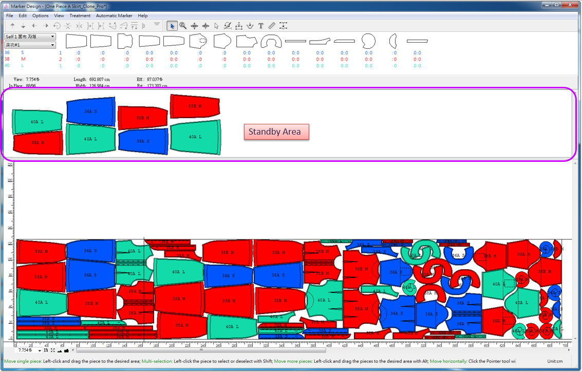
As shown above, PAD System™ Marker Design software interface consists of menu bar, tool bar, chart, standby area, simulation area, working area rulers, info bar on lower-right corner (it shows the coordinates and current unit). Each section and its functions will be introduced later in detailed.
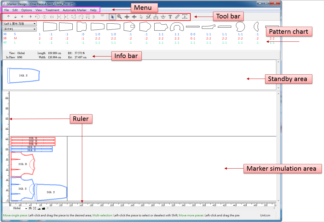
Menu Bar
Menu bar includes: File, Edit, Option, View, Treatment, Automatic Marker and Help.
Note
For more information about the function of each menu, please refer to Chapter 2.

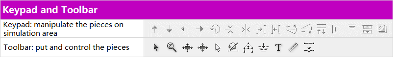
Keypad and Toolbar
PAD System™ Marker Design provides keypad and toolbar for user to treat the pattern pieces.
Note
For more information about the function of tools, please refer to Chapter 3.
Chart
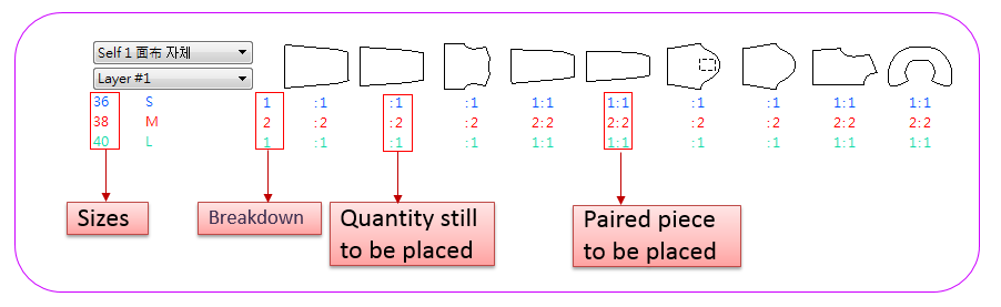
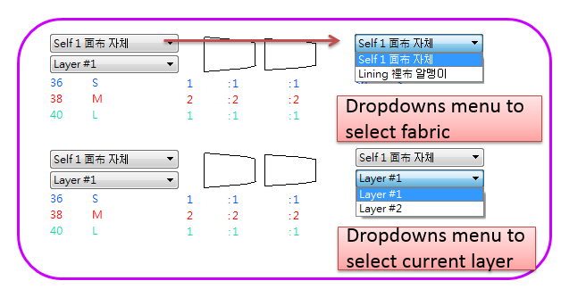
Chart is at the top of the working area, showing pattern styles, sizes and quantities. Systerm preset the different colors for sizes, user can change as desire.
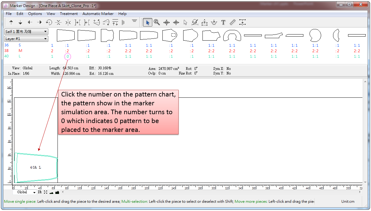
Click the number under the desired pattern piece, the corresponding piece will be placed in the simulation area.
Then user can use the keypad and tools to manipulate the pattern pieces.
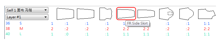
When the pointer move to the pattern piece, the name is shown:
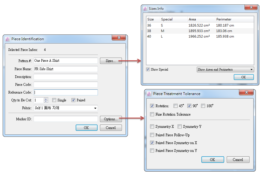
Double-click the pattern piece to open the [Pieces Identification] Dialog Box, user can modify the information:
Info Bar
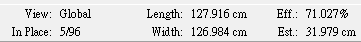
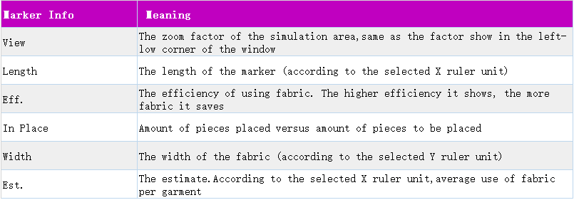
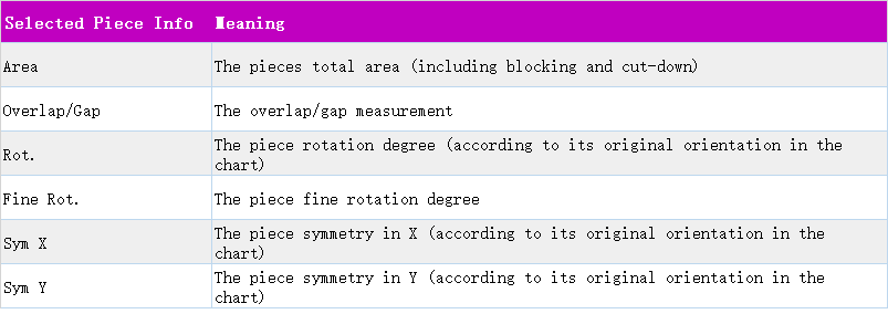
Info bar always shows the information about the marker and selected piece(s).
Infomation includes:
Marker information
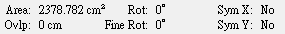
Information about the selected piece(s) in the simulation area
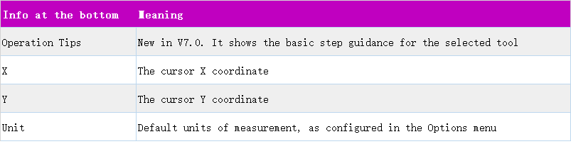
Information on the bottom of the working area

Standby Area
User can put the piece in the Standby Area temporarily.
Standby Area is a space between the Chart and the Simulation Area.
Except
Fill a Hole tool, the rest of the tools can be applied on the standby area. However, all pieces left in the Stand By Area are not plotted or calculated by the estimate.
Note
For more information about Standby Area, please refer to corresponding section in Chapter 2 [View] Menu introduction.
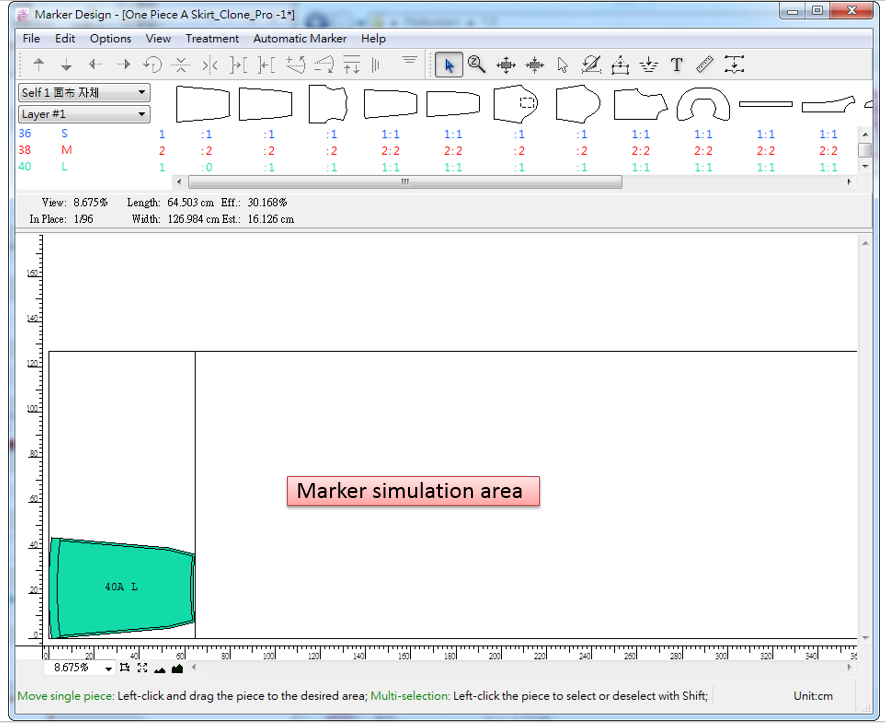
Simulation Area
This area is for simulating the nesting. User can use the tools and keypad, to manipulate the pattern piece(s) in the simulation area.
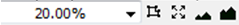
Zoom Menu
You can find the Zoom Menu in the lower-left corner of the main application window. It includes 5 functions:
The Zoom Menu is for controlling the zoom level:
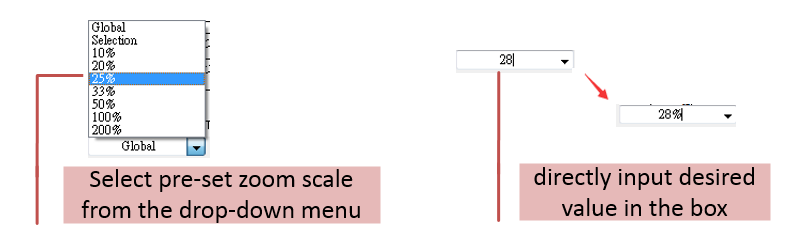
You can select the pre-set zoom scale from pull-down menu or directly input desired value in the box and press Enter key.
Zoom on Selection: enlarge the view of the selected piece(s) and show it at the center of the working area.
Global View: displays all the visible pattern piece in the working area.
Zoom Out: reduce the view of all the visible pattern piece in the working area.
Zoom In: enlarge the view of all the visible pattern piece in the working area.
The scaling ratio range is from 0.05% to 2000%.
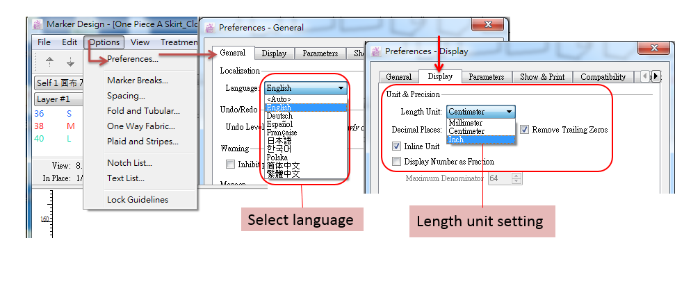
Set Interface Language and Unit before Working
Keyboard
Shift key
Make multi-selection with tool.
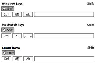
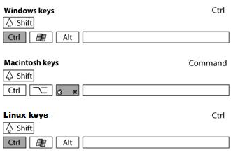
Ctrl (Windows/Linux) or Command (Macintosh) key
Temporarily show the Pointer tool while other tool of toolbox is selected.
Make a continuous selection from the list (like Marker Assistant)
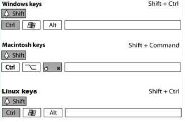
Shift+Ctrl (Windows/Linux) or Shift+Command (Macintosh) key
Select more than one element when another tool is activated.
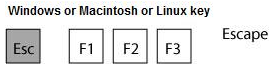
Esc key
Quit the dialog box or cancel any action in progress.
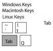
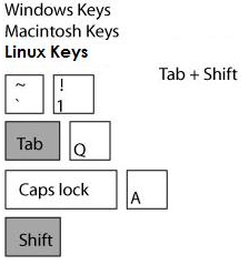
Tab key
Make a quick move in the zoom menu on the lower-left corner of the application interface.
Make a quick move from one field to the next or button to another in a dialog box.
Tab+Shift key (Windows/Linux/Macintosh)
Press Shift and Tab together to move backward to previous field.
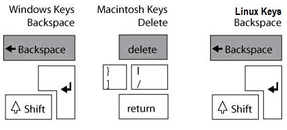
Backspace (Windows/Linux) or Delete (Macintosh) key
Delete the selected piece. The deleted pattern piece will go back to the Chart and the quantities will be recovered.
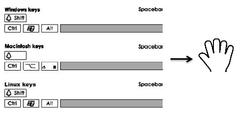
Space
Enlarge/reduce the views of standby area and simulation area.
Enlarge/reduce the views: hold down the Space key without releasing, a hand icon appears. Then roll the mouse wheel up or down to enlarge/reduce the view.
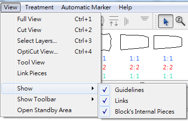
Guideline
Allow user to pull out guidelines to assist with placing pieces and indicate plaid and striped fabric; it helps make assignment when nest pieces, which improve the accuracy; and it restrains the range for nesting.
To show the guidelines, click menu [View]-[Show]-[Guidelines].
Make Guidelines
User can make guidelines by two ways: pull out or enter values.
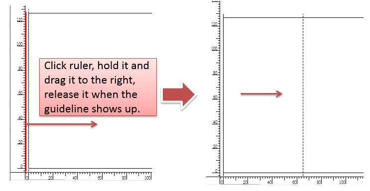
Pull out guidelines
Select
Pointer tool;
Left-click the Y axis (or X axis) without releasing, drag out a vertical or horizontal line to desired location. Then release the mouse button.
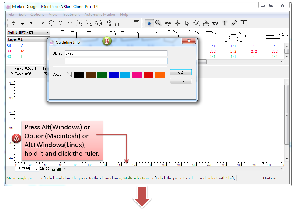
Enter value
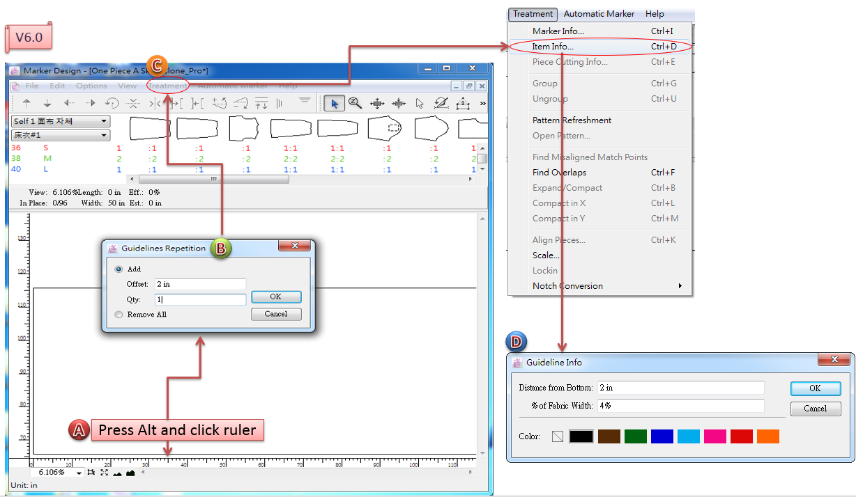
Hold down Alt (Windows) or Option (Macintosh) or Alt + Windows (Linux) key, left-click the ruler (X or Y axis);
A dialog box appears; enter desired value and select color, click [OK] button to finish.
Note
In V7.0, we optimize the guideline info dialog box, combine setting guidelines and selecting colors together, which simplifies the operation. In V6.0, user need to go to Menu [Treatment]-[Item] info, to select the color.
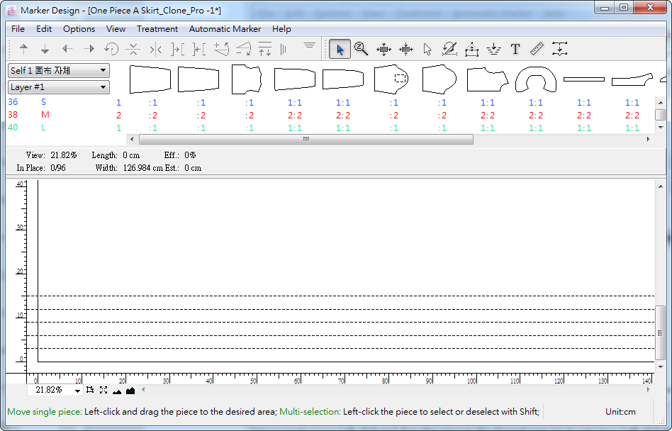
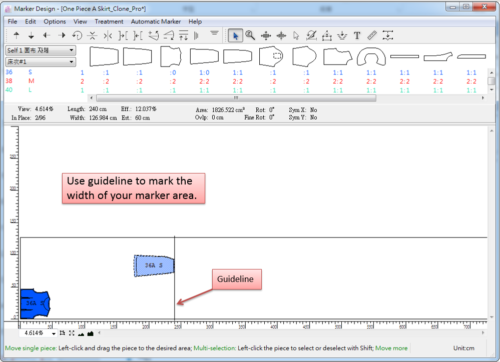
Estimating with a Guideline
For PAD Marker Design can set the width of the simulation area only and do not limit the length, user can make guidelines to set an a minimum area where user place pieces on the Fabric Simulation Area.
Make guidelines according to the two ways introduced above, to set a minimum area;
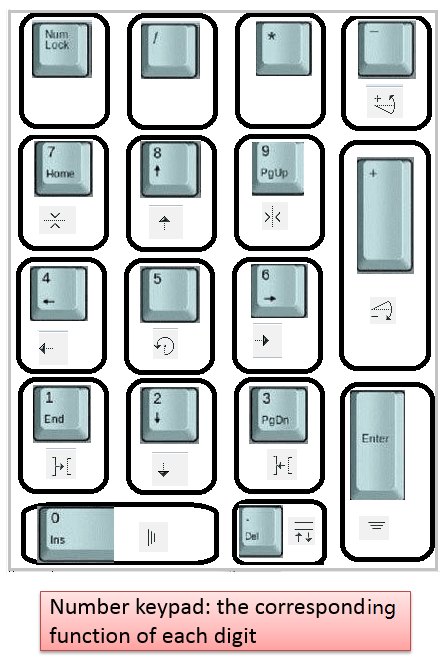
Select desired piece, use numberic keyboard to control the piece. The piece move inside the minimum area.
Note
During nesting by manual, if you want to move the piece(s) in the simulation area, you can’t use the arrow keys on the key board. Only the numberic keyboard introduced above is available.
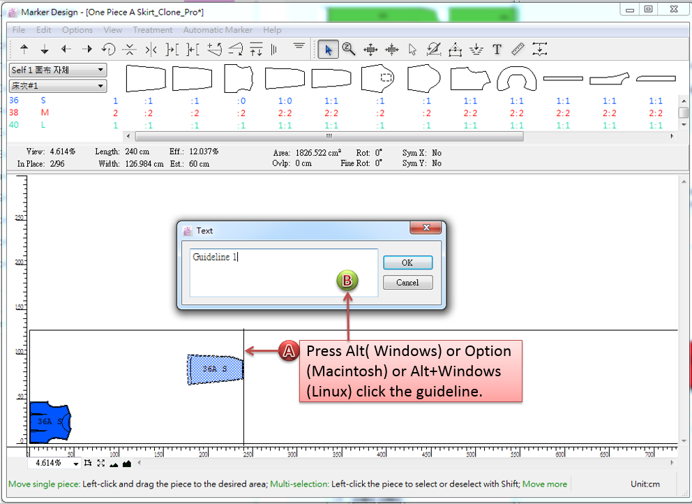
Add Text to Guidelines
Select
Hold down Alt (Windows) or Option (Macintosh) or Alt + Windows (Linux) key, and click the desired guideline, to open the dialog box;
Enter text in the dialog box and click [OK] button to finish.
Remove a Guideline
Select the desired guideline by
Intelligent Dialog Box
PAD System™ Marker Design provides any dialog box with intelligent calculation. You can put + (plus), - (minus), x (multiply), / (divide) to calculate measurement, also convert unit automatically.
Do calculation with + (plus), - (minus), x (multiply), / (divide)
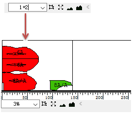
Take Scale Menu as an example:
Enter “1+2” in the dialog then press Enter, the system calculates and executes the result automatically.
Convert unit automatically
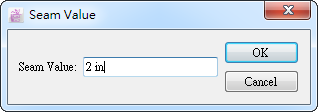
Take
Cut with Angle tool as an example:
The current unit is cm, when enter 2in, the system conters unit and calculates the result automatically:
Add Some Function for Image on the Piece
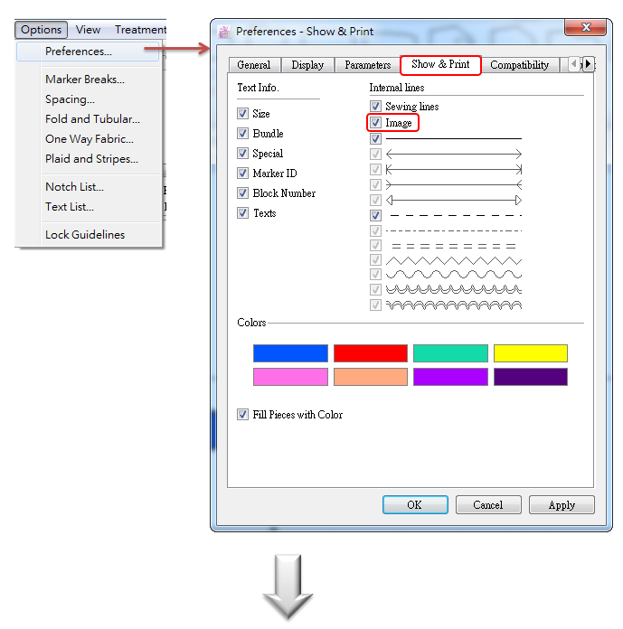
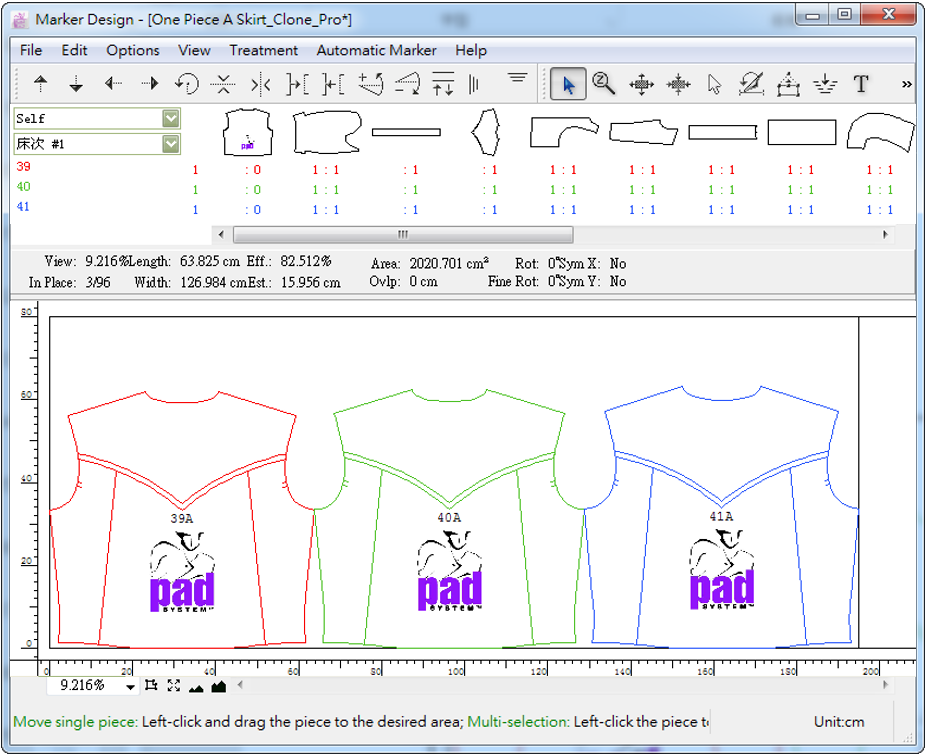
Allow users to show images added on desired piece in the simulation area.
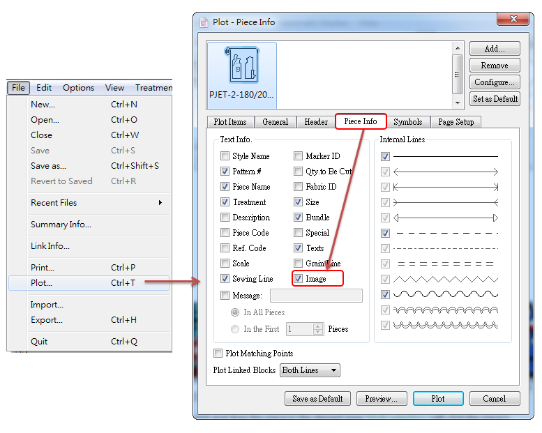
Click menu [Options] - [Preferences] to open dialog box. Click [Show & Print] and select [Image].
Note
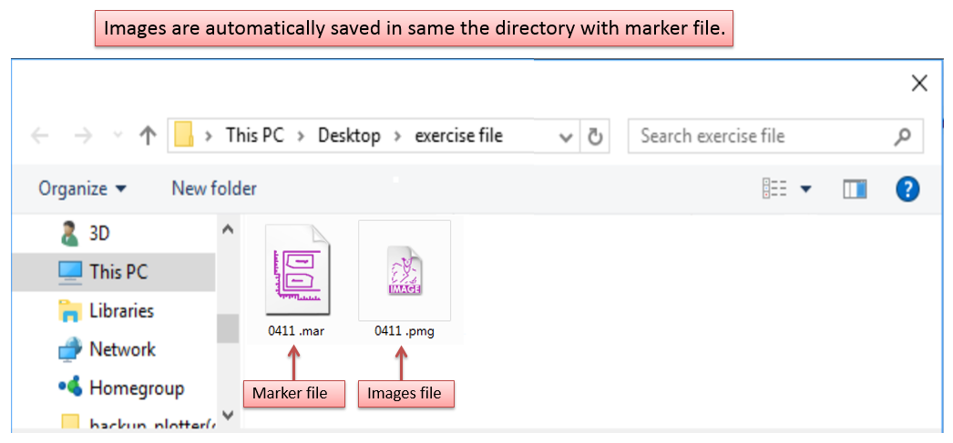
Pattern file and image file need to be in the same directory. When users use the pattern file to build new marker, it will check if the pattern file contains images and read them automatically.
Save image file
When you save the marker file (.mar), the image will also be save under the same path (marker file and image file are saved in the same directory). Image format is .pmg, shown as following picture:
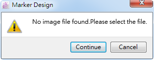
Missing image file
If:
change the name of marker file (.mar );
change the name of image file (.pmg);
the marker file (.mar) and image file (.pmg) are in different path (Error moving file or lost sending file);
then it will miss the image file (that’s to say, fail to read corresponding image file while open the marker file), dialog box appears:
Continue - select image file manually;
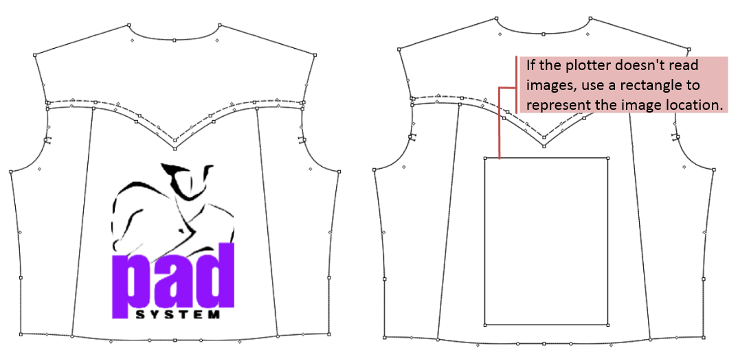
Cancle - close dialog box, and replace the image with a rectangle shape.
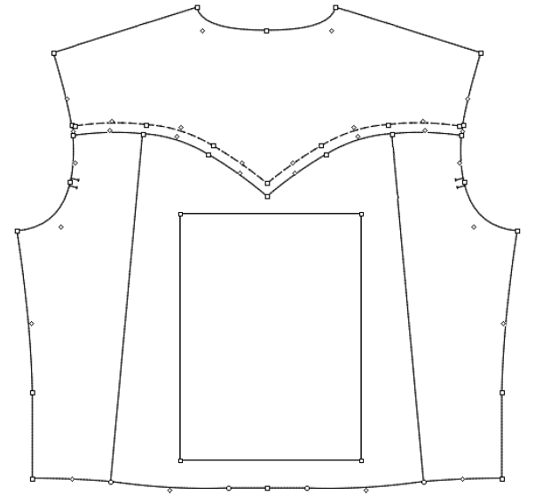
Export the pattern file with images as other formats
Export the pattern file with image as other formats, like DXF-AAMA, DXF-ASTM, Illustrator (.txt), Plotting File (.plt). Then the image will be shown as rectangle:
Print image
Allow users to print the image while print the marker file.
Note
Now PAD OEM Plotter & HP (Hewlett Packard) Printer can print the pattern piece and its images. Other printer or plotter can print its frame only.
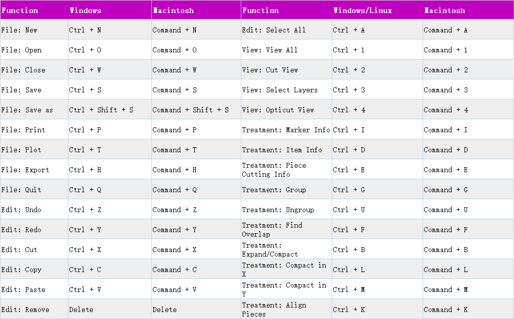
Hot Key Shortcuts
PAD System™ Marker Design provides many default hot key shortcuts for users, meanwhile, it also allows users to customize the hot keys, increase the efficiency of nesting.
Hot keys list as follows:
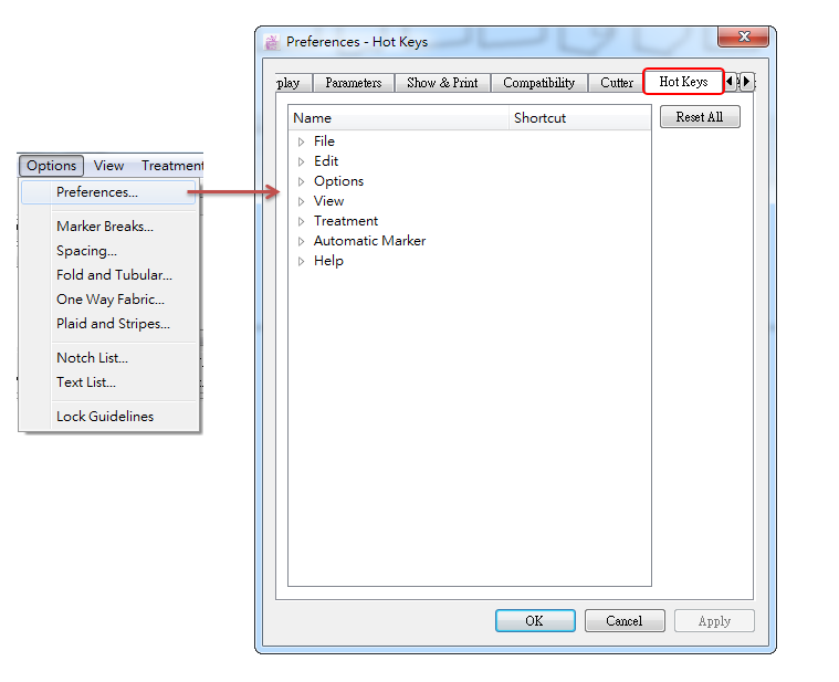
If you want to change the hot key, please go to menu [Option]-[Preferences…]-[Hot Keys]. For more information about how to change, please refer to Chapter 2, Option Menu Introduction.