[View] Menu
[View] Menu includes functions as following:
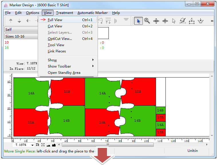
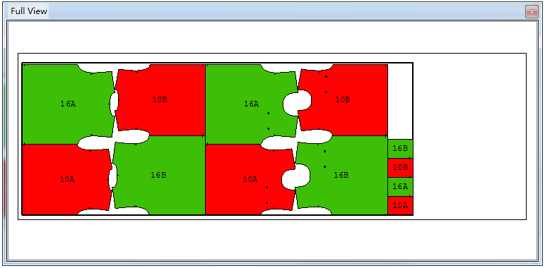
Full View
Allow user to see the entire marker:
Click
button on the upper-right corner, or click menu [View]-[Full View] to close the full view window.
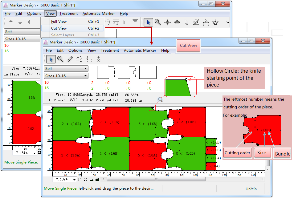
Cut View
Click this item to turn to Cut View environment. Under Cut View environment, user can check and modify the knife starting point, knife sequence, or add external punch hole with tools.
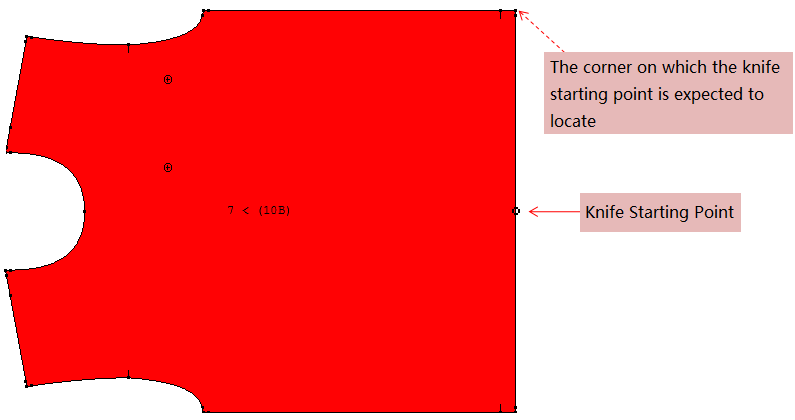
Tools in Cut View toolbar
Pointer
Select one or many pieces in Cut View.
Zoom In/Out:
To reduce or enlarge the general view:
Zoom In:select the tool, left-click the position you wish to zoom in. Keep left-clicking till you get desired scale; or left-click without releasing the mouse button and drag a rectangle covering the position you wish to zoom in, then release the mouse button.
Zoom Out:select the tool, hold down Alt key, the arrow converts to a minifier glass, click the area you want to reduce.
Ruler
Measure the distance between two points. How to do: select the tool, click the first reference point and then the second one. The “Point to Point Distance” dialog box appears to show the measurements.
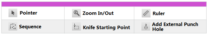
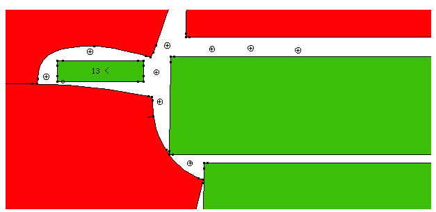
Sequence
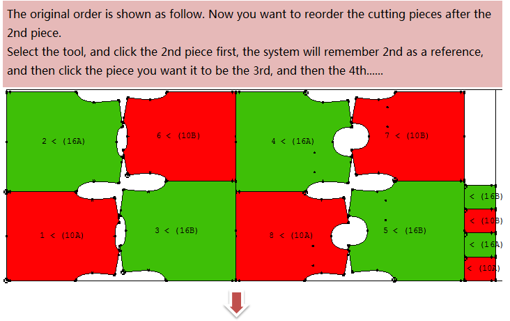
By default, the numbering of the pieces is laid out in a way to minimize the movements of a robotic cutter. To change this order, use the Sequence to reorder pieces for pattern cutting.
How to do:
Select the Sequence tool.
Click the pieces in the order you wish them to be cut: for example, when you wnat to start from the 3rd piece, then click the 2nd piece first, the system will remeber to take 2nd as a reference, and then click the new 3rd piece and 4th…. piece
For example:
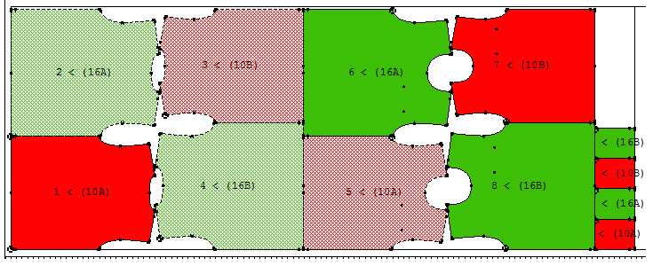
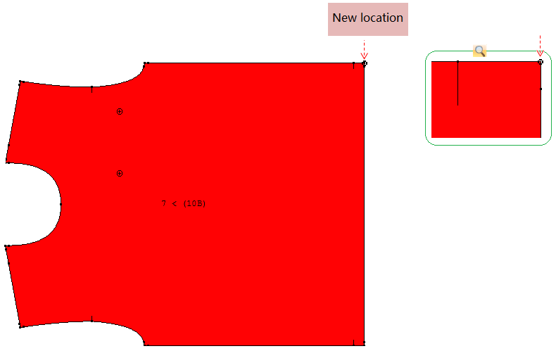
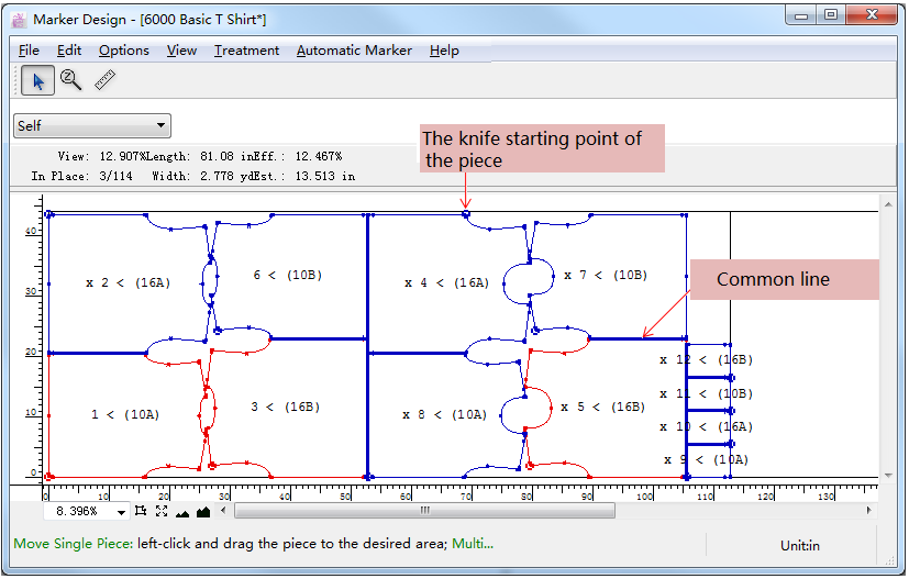
Knife Starting Point
The Knife Starting Point tool enables you to reposition the starting point for each piece. A start point should be positioned in a corner and cannot be on a notch.
As following picture is shown, the nifte starting point is on the front center hem, now it needs to be relocated to a upper-right corner:
How to do:
select
click the new starting point of the piece
Add External Punch Hole
This tool was mentioned when we introduced Exporting Cut File in File Menu section
option.
Some cutters use a vacuum to keep the fabric stable during cutting. By adding punch holes between your pieces, the pieces adhere better to the cutting table, thus keeping the pieces more stable during cutting.
How to add external punch hole:
select
left-click the desired location between pieces to add punch hole,
: external punch hole.
Note
After adding external punch hole, select
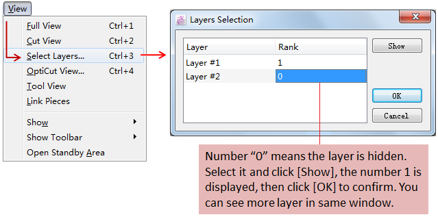
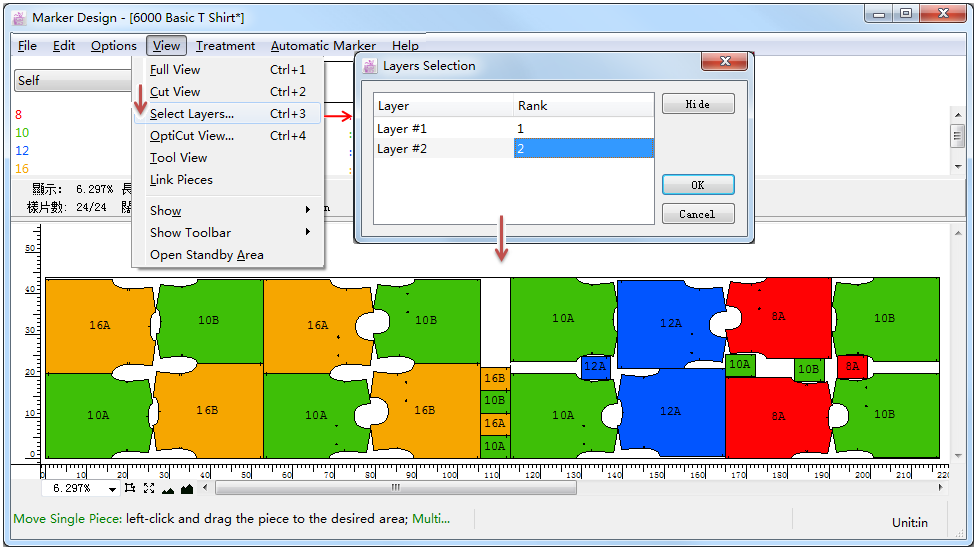
Select Layers
Allow user to view more than one layer in the same simulation area.
Click [Select Layers…], open the dialog box:
For example:
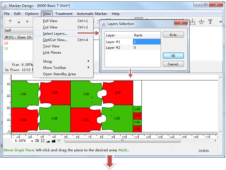
Note
If you select to view view more than one layer in the same simulation area, then the layers will be printed at the same time. If you don’t want to print more layers in the same time, then select to hide the undesired layer number in the dialog box, or select the settings in the Print dialog box.
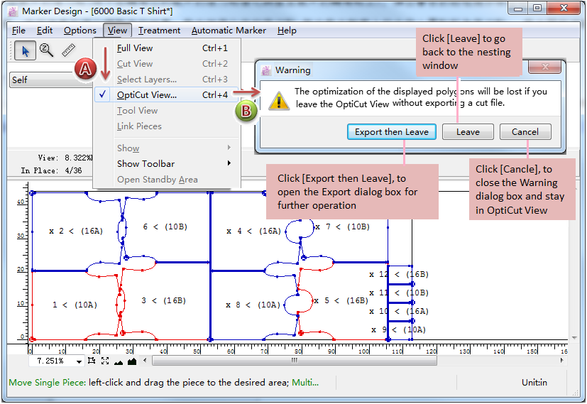
Opticut View…
After completing a marker and exporting a marker file, open OptiCut View environment to optimize and adjust the knife point(relocate the knife point not on the corner to the piece’s corner), and make common cutting according to actual situation (that’s to say, according to the settings, the adjacent lines of pieces become common lines, the cutter cuts common lines once.)
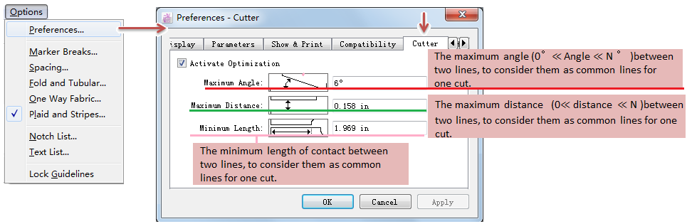
Note
Before using OptiCut View, go to menu [Options]-[Preferences]-[Cutter], select “Activate Optimization”, and enter desired values:
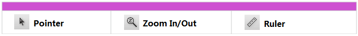
Tools in OptiCut View
Select one or many pieces in Cut View.
To reduce or enlarge the general view:
Zoom In:select the tool, left-click the position you wish to zoom in. Keep left-clicking till you get desired scale; or left-click without releasing the mouse button and drag a rectangle covering the position you wish to zoom in, then release the mouse button.
Zoom Out:select the tool, hold down Alt key, the arrow converts to a minifier glass, click the area you want to reduce.
Measure the distance between two points. How to do: select the tool, click the first reference point and then the second one. The “Point to Point Distance” dialog box appears to show the measurements.
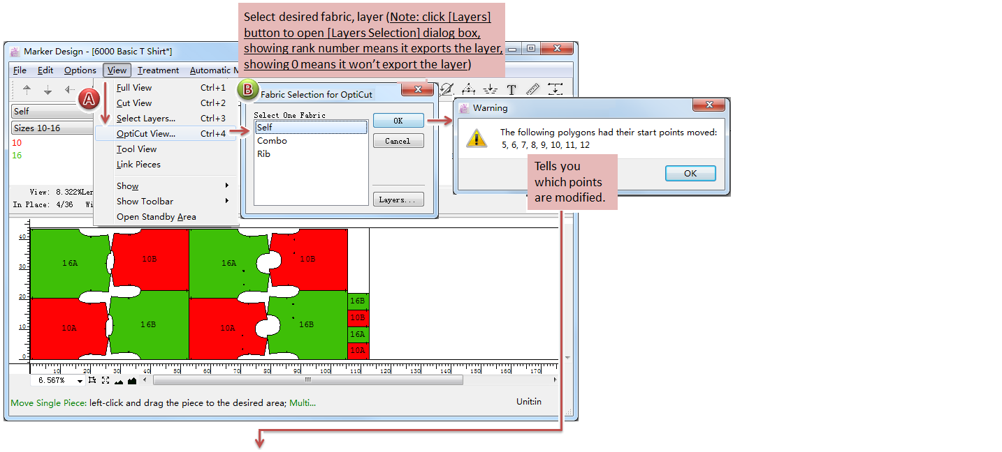
Steps to open OptiCut View for marker optimization:
before exporting the finished marker file, click [Vie]-[OptiCut View];
select the desired fabric and layers in OptiCut View
the system adjusts the knife points automatically (relocate the knife point not on the corner to the piece’s corner). Dialog box appears to show you which knife points of pieces have been modified. Click [OK] to enter OptiCut View environment;
In OptiCut View environment, you can see result: the knife point of piece(the hollow circle on the contour is the knife point), and the thick line between pieces is the common line.
Now you can export it:
click menu [File]-[Export], select export file fomat, for more information about exporting, please refer to [File] menu;
click menu [View]-[OptiCut View…], the dialog box appears:
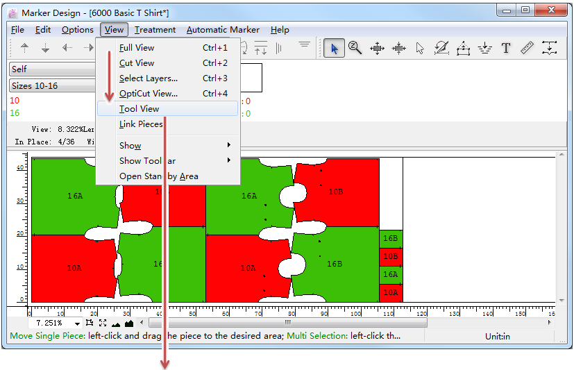
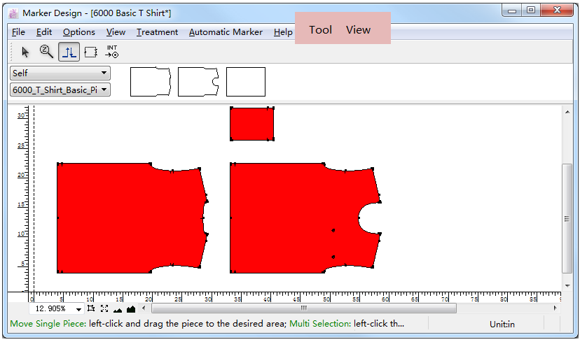
Tool View
Open tool view environment. In this environment, user can set the cutting command: control the lift and plunge of knife, set the symmetrical cut, and set the internal cutting start point.
Click [View]-[Tool View…] to enter the environment:
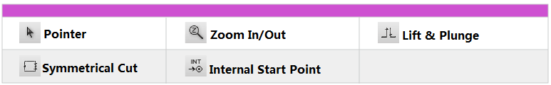
Tools in Tool View
Select one or many pieces in Cut View.
To reduce or enlarge the general view:
Zoom In:select the tool, left-click the position you wish to zoom in. Keep left-clicking till you get desired scale; or left-click without releasing the mouse button and drag a rectangle covering the position you wish to zoom in, then release the mouse button.
Zoom Out:select the tool, hold down Alt key, the arrow converts to a minifier glass, click the area you want to reduce.
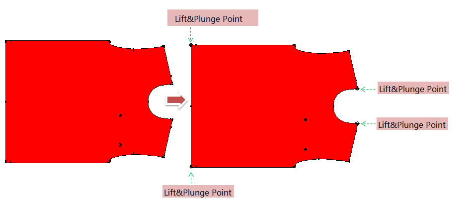
Lift and Plunge
The Lift and Plunge tool tells the cutting knife where to lift, pivot and plunge while cutting a piece. Commonly add lift&plunge point on the corner(corner angle ≤90°).
How to create lift&plunge point:
select
in the simulation area;
left-click the desired location, the Lift&Plunge mark appears.
How to delete lift&plunge point:
select
hold down Alt (Windows) or Option (Macintosh) or Alt+Windows (Linux), the pointer becomes
in the simulation area. Left-click the the Lift&Plunge mark to finish deleting.
Note
If view of working area is not large enough, use Zoom In/Out tool to enlarge the view (or hold down Space key and roll the mouse wheel up to enlarge the view).
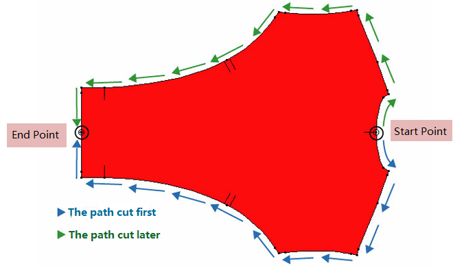
Symmetrical Cut
As manufacturing demand, some pieces need to be symmetrically cut for accuracy, so use
How to enable a symmetrical cut
select
in simulation area;
click the point where you wish the knife to start, and the pointer in the simulation area become
;
click the point where you wish the knife to end;
the knife will cut one in one direction, until it meets the end point. It will return to the starting point and cut the other side in the other direction, until it meets the end point again.
How to remove a symmetrical cut point:
select
hold down Alt (Windows) or Option (Macintosh) or Alt+Windows (Linux) key, and the pointer becomes
Note
If view of working area is not large enough, use Zoom In/Out tool to enlarge the view (or hold down Space key and roll the mouse wheel up to enlarge the view).
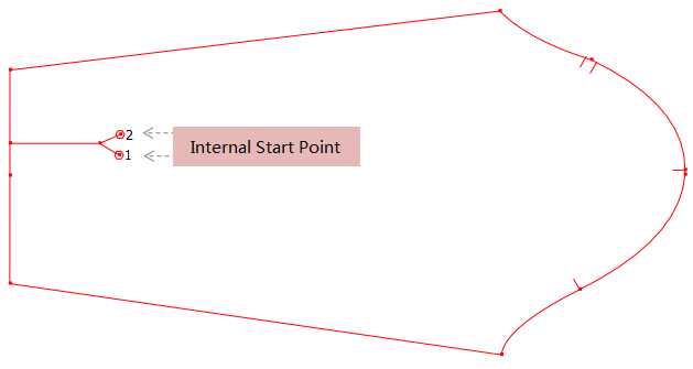
Internal Start Point
select
click the internal segment where you wish the knife to start, repeat the same step to another the internal segment where you wish the knife to start. The number appears next to the start point indicated the cutting sequence.
How to remove the internal start point:
select
hold down Alt (Windows) or Option (Macintosh) or Alt+Windows (Linux) key, and the pointer becomes
Note
If view of working area is not large enough, use Zoom In/Out tool to enlarge the view (or hold down Space key and roll the mouse wheel up to enlarge the view).
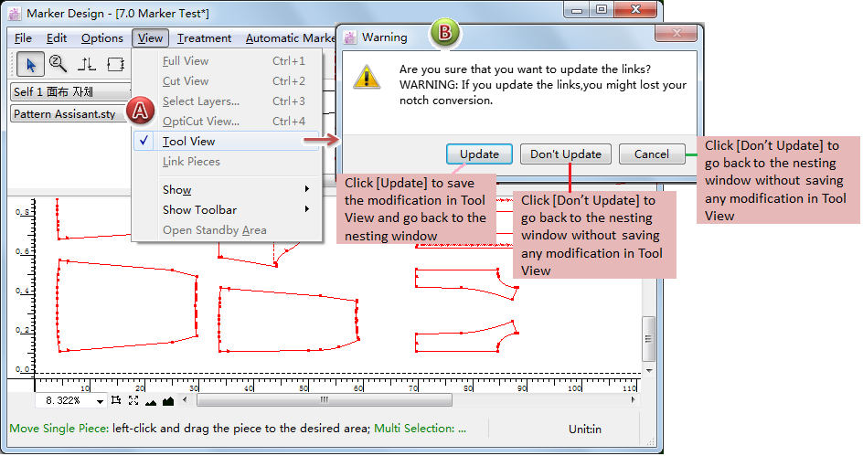
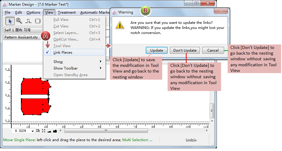
How to save the modifications mentioned above in Tool View
After finishing the settings, click [View]-[Tool View] to open the warn dialog box to save the settings:
Link Pieces
Link Pieces enables you to place match points and link them together. The pattern pieces with match points and linked match points get aligned when placed on plaid and striped fabric.
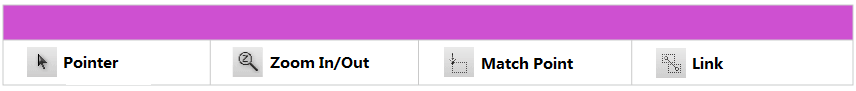
Tools in Link Pieces
Select one or many pieces in Cut View.
To reduce or enlarge the general view:
Zoom In:select the tool, left-click the position you wish to zoom in. Keep left-clicking till you get desired scale; or left-click without releasing the mouse button and drag a rectangle covering the position you wish to zoom in, then release the mouse button.
Zoom Out:select the tool, hold down Alt key, the arrow converts to a minifier glass, click the area you want to reduce.
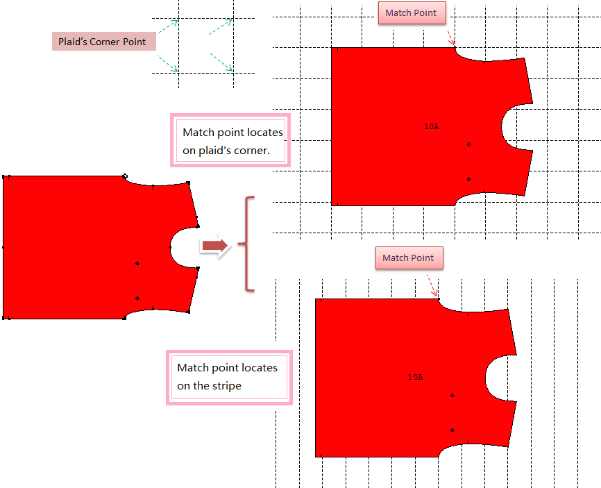
Match Point
How to create a match point: select
, then left-click an existing point on the pattern piece, a small circle forms around the point to indicate that it is a match point.
If start automatic marker after saving the settings, then:
plaid fabric: the match point locates on the corner point of the plaid(each plaid with four corner points);
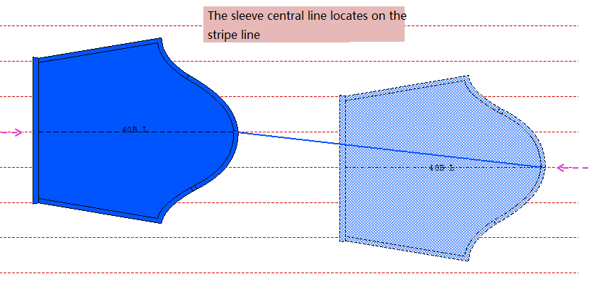
stripe fabric: the match point locates on the stripes;
How to remove a match point: select
Note
If view of working area is not large enough, use Zoom In/Out tool to enlarge the view (or hold down Space key and roll the mouse wheel up to enlarge the view).
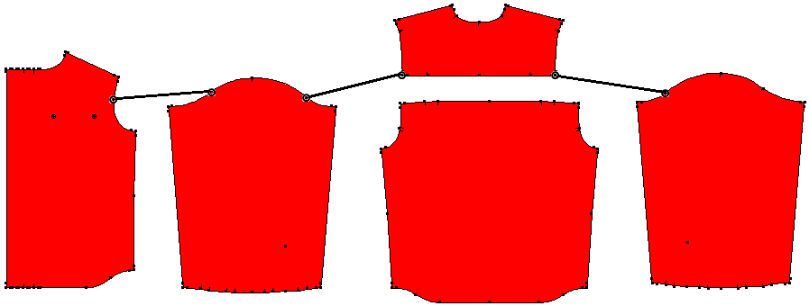
Link
The Link tool enables you to create links between various predetermined points.
For example, the plaid shirt needs to be matched plaids and stripes, according to the atcual requrement, make links as follows:
How to create links between points:
select
left-click a point, and the “1” becomes a “2”, left-click another match point, a link forms via a line connecting both pieces;
the “2” becomes “1” again, informing you that the tool is ready to create another new link;
after linking, set Link Properties as desired.
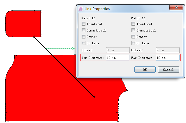
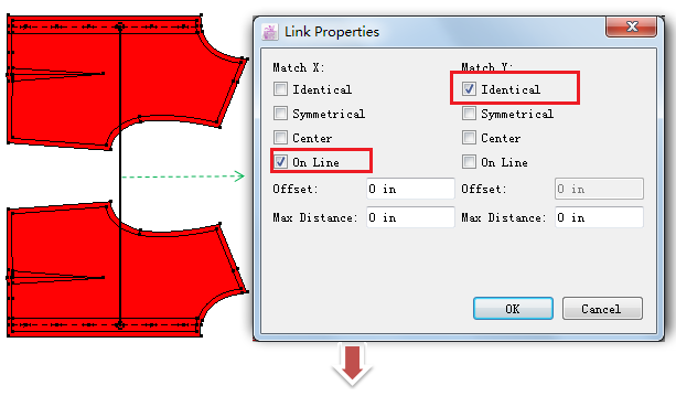
How to set Link Properties:
select
double-click the link line, the dialog box appears;
enter value or select desired option:
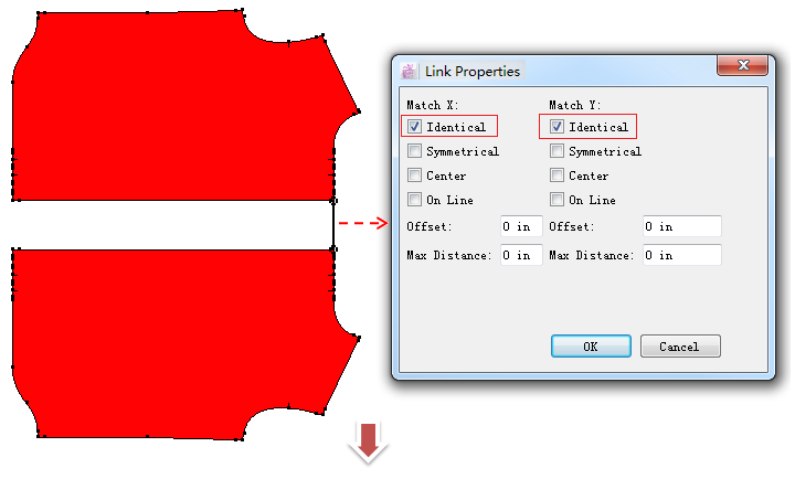
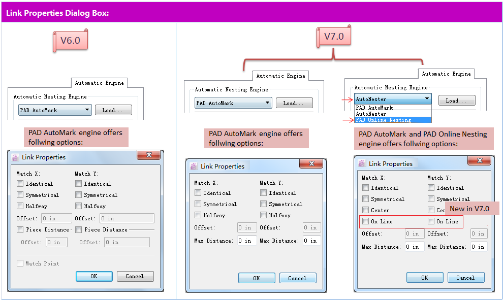
Examples of the options in Link Properties Dialog Box:
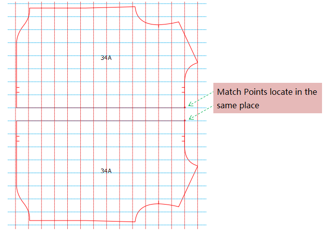
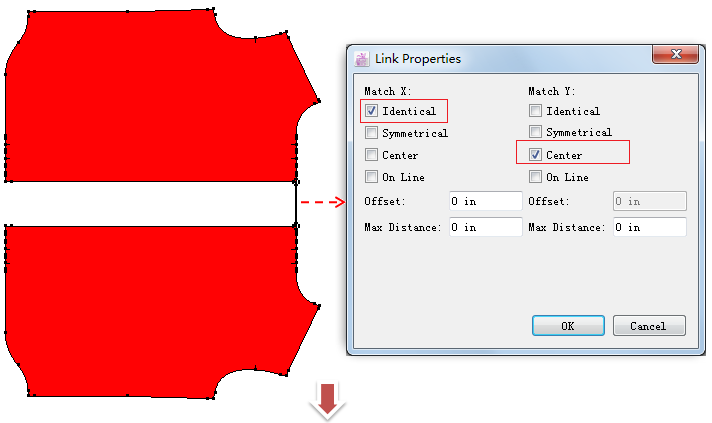
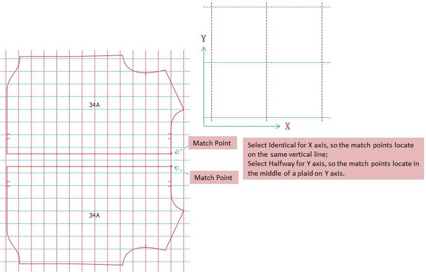
Identical: match point places on any Intersection points.
Like:
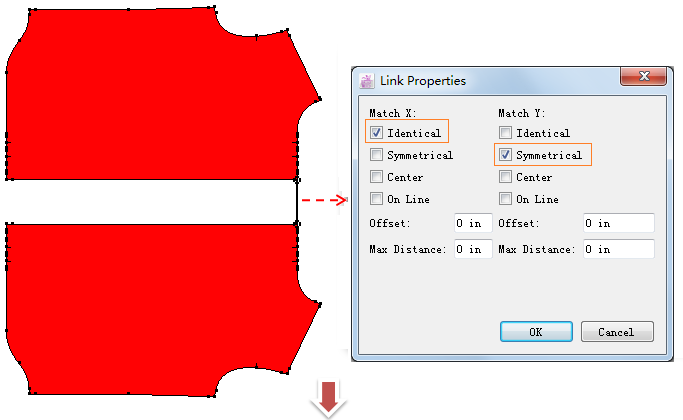
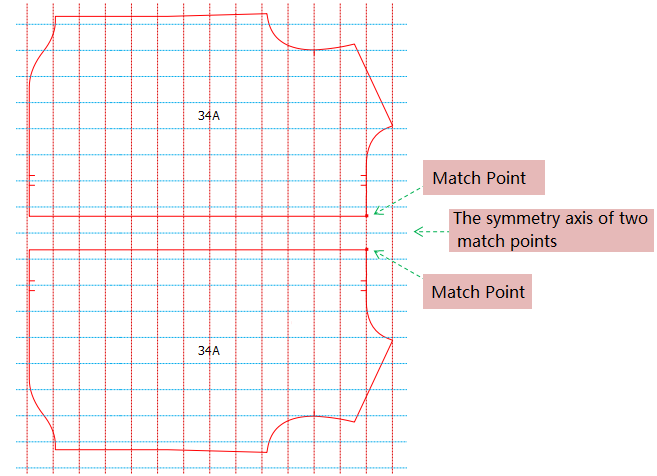
Symmetrical: The neareast horizontal line between the match points of pieces is the symmetrical axis. Two match points are symmetrical.
For example:
Halfway: the match points locate in the middle of the plaid or stripe in paired piece
For example:
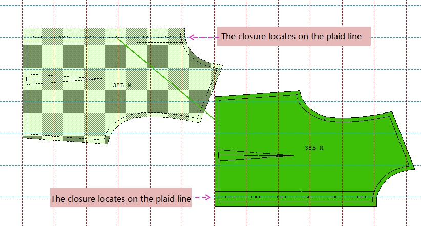
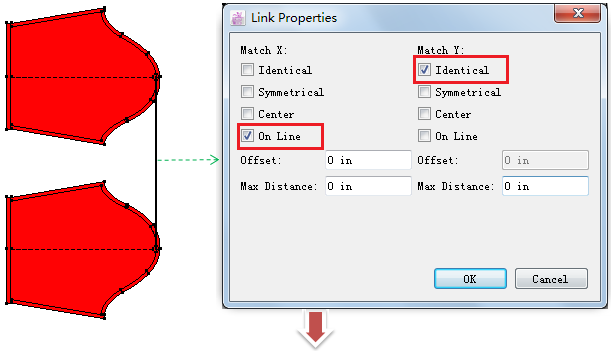
On Line: New in V7.0, for using in AutoNester 、PAD Oline Nesting engine only.
The match points locate on the lines of plaids or stripes of the fabric only.
For example:
Plaid Fabric:
Stripe Fabric
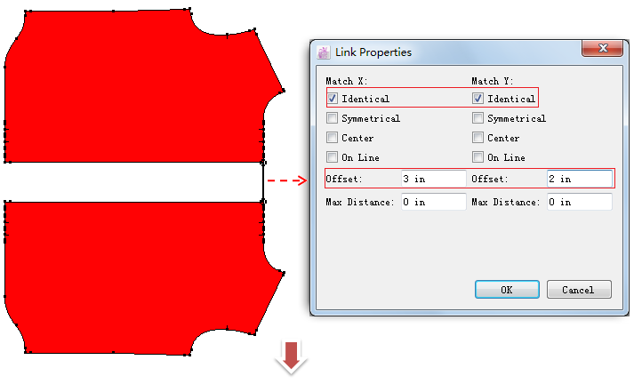
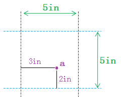
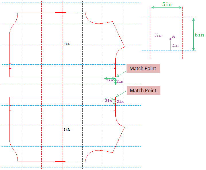
Offset: define the match point to specify position.
For example: the plaid is 5*5 in, and I want to locate the match points on the point a of plaids shown in the image:
Then set the link like:
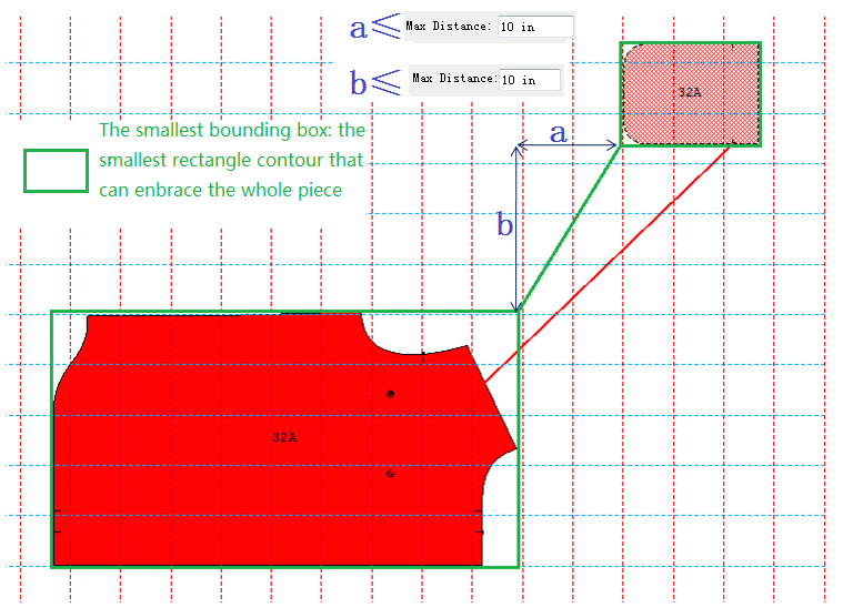
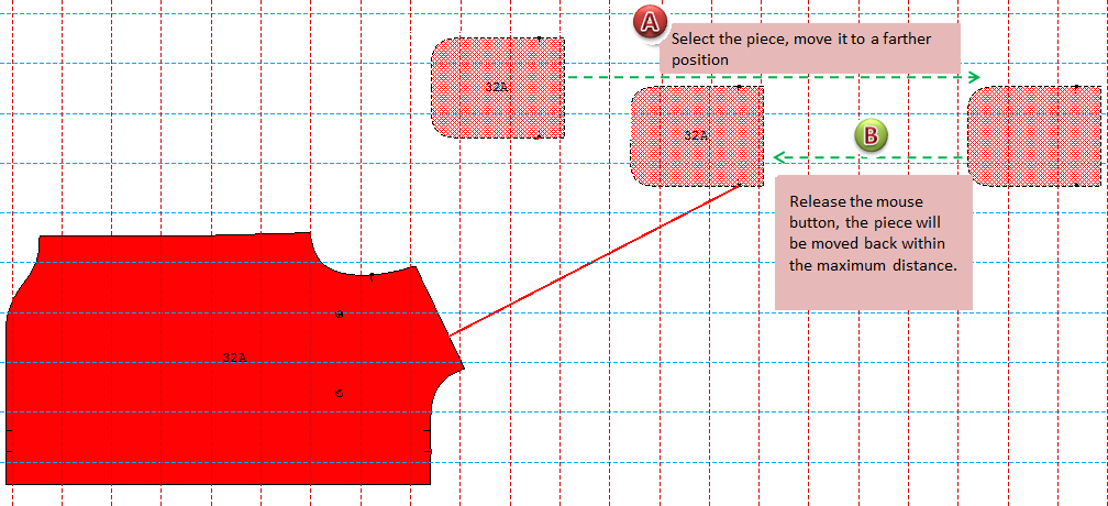
Max Distance: to enter a value limit the space between two piece.
Calculation of the max distance: enclose each piece with the largest rectangle. The max distance should includes the shortest distances to X axis and to Y.
For example:
This function is for manual nesting only, not for automatic nesting.
After placing the master piece, the sub-piece will be moved within the maximum distance.
Note
When you are linking piece, click the master piece first and then the sub-piece.
As shown in the following image, the body is the master piece, the pocket is the sub-piece. Using Pointer tool, left-click the pocket without releasing the mouse button, move it to the position out of the maximum range, the pocket will go back within the maximum distance.
How to remove the link:
select
hold down Alt (Windows) or Option (Macintosh) or Alt+Windows (Linux) key, the pointer becomes

How to save your settings in Link Pieces view
After finishing settings, click menu [View]-[Link Pieces], the dialog box appears:
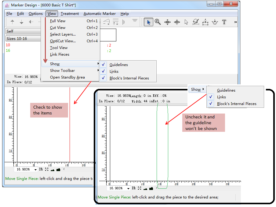
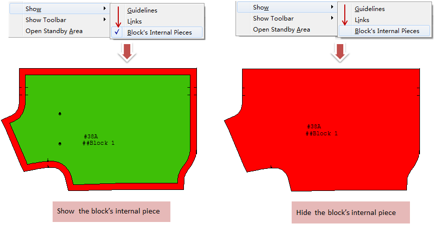
Show
Allow user to show or hide the “Guideline”, “Link” or “Block’s Internal Pieces” in the simulation area. Click to check the item,
appears to show feature; click once more the item, the tick mark disappears to hide feature.
Guideline: show or hide the guidelines.
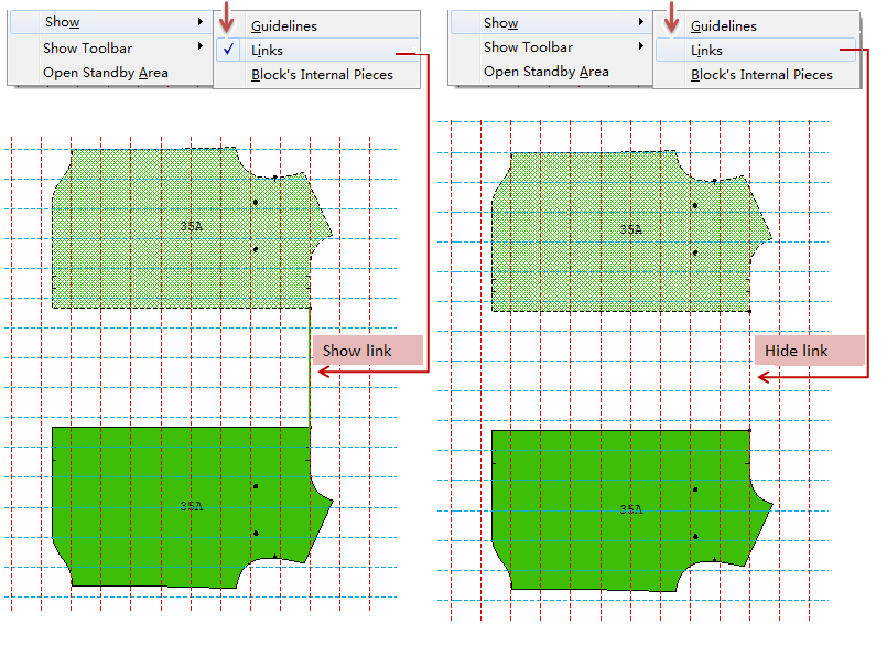
Link: show or hide the link lines. For more information about Link Piece, please go back to last section. If select this item, the link line(s) will be shown in the working area.
Block’s Internal Pieces: show or hide the internal blocks:
Note
for more information about Block Piece and Block Piece Link, please refer to Chapter 3 Block a Piece tool.
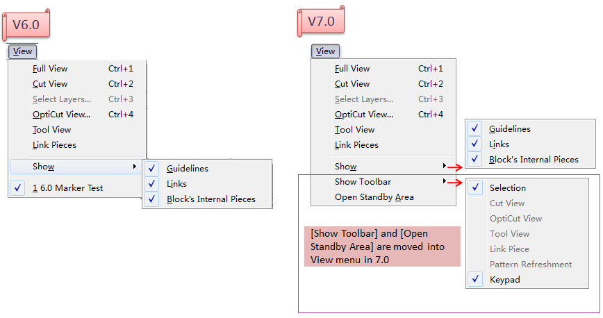
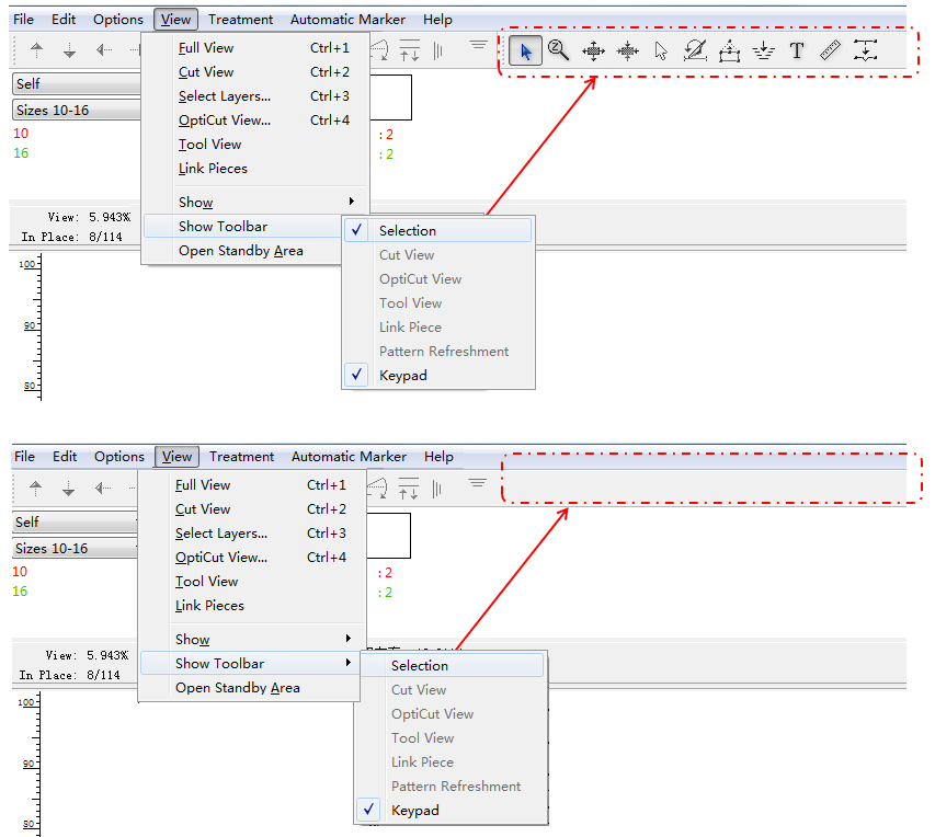
Show Toolbar
Allow user to show or hide the toolbar.
Note
the original position of this item is in the [Options] menu. In V7.0, it is moved to the [View] menu.
The item is shown, the check mark (✓)
For example:
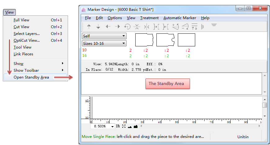
Open/Close Standby Area
Click the Open/Close Stand By Area item in the Options menu to show or hide the Standby Area:
Note
In V7.0, the position of [Open/Close Standby Area] item is moved from [Options] menu to [View] menu.
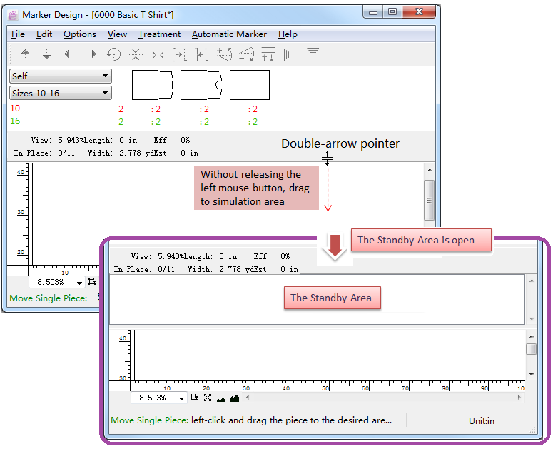
The other way to open/close Standby Area:
select
move the pointer to the double line and the pointer becomes double-arrow, left-click to drag the line to simulation area;
release the mouse button, the standby area is open.
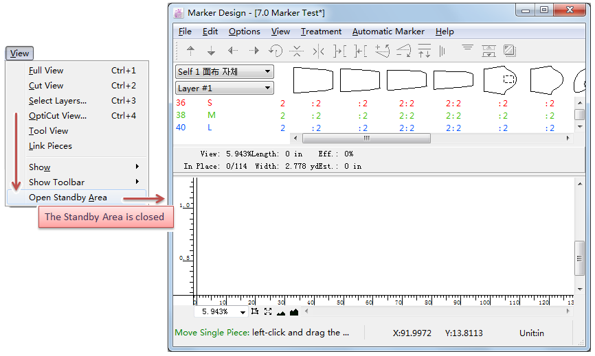
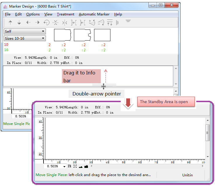
If you want to close the standby area, then:
select
click and drag the double-line to info bar;
release the mouse button, the standby area is close.