Chapter 3: Pattern Design Tools
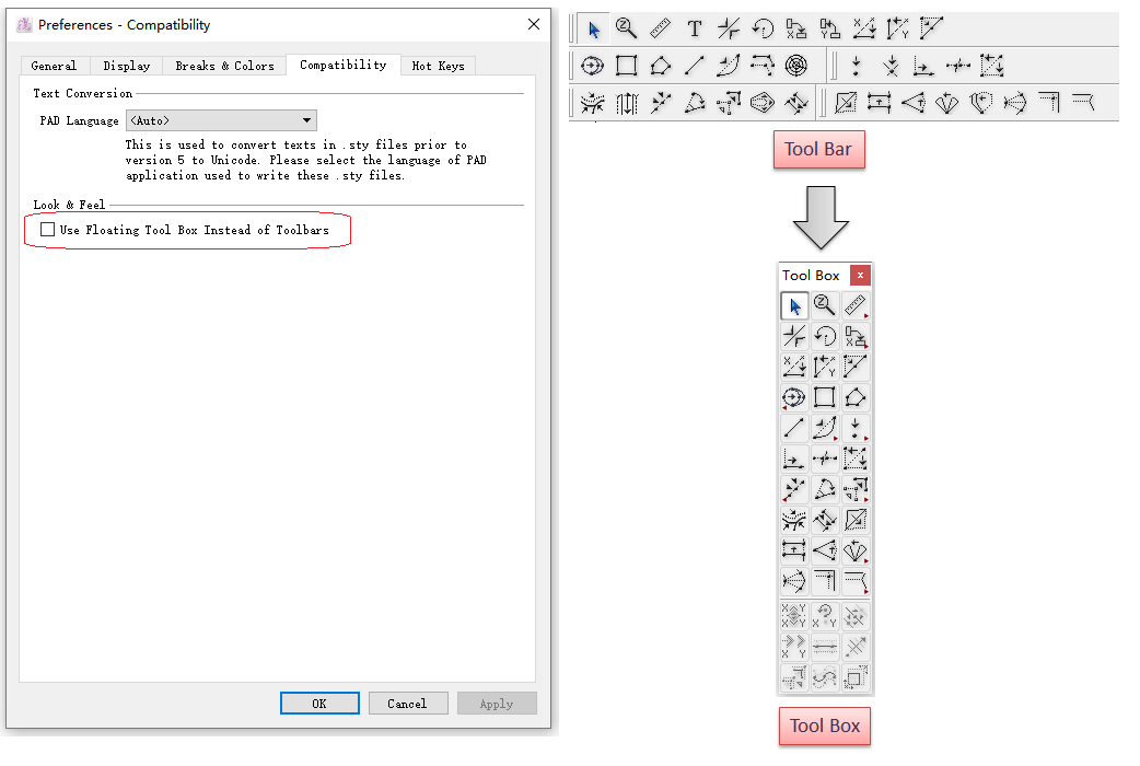
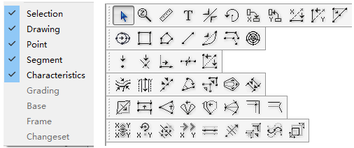
Before V5.0, the tools are listed in box. Now they are shown in tool bar. Users can select to show tool bar or tool box as they wish.
Click Menu [Option] - [Preference]- [Compatibility], select [Use Floating Tool Box Instead of Toolbars], all the tools are shown in tool box.
Users can make or modify their pattern pieces by using the tools.
Pattern pieces can be modified using different views: Plan, Pieces, Clone and Grading.
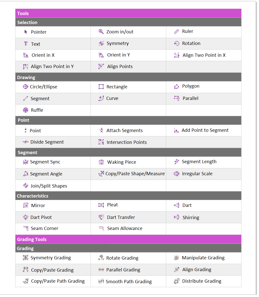
Function of each tool in the Toolbox / Toolbars:
 Pointer
The Pointer tool
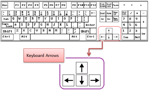
Move element(s) by using keyboard arrows
Select the Pointer tool
Select the element(s) you wish to move
Use the directional arrows (Up, Down, Left, Right) to move the elements to the desired location
Note
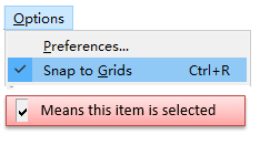
Select the [Snap to Grid] item in the Options menu, to move elements according to the active grid.
For more information about [Snap to Grid], please refer to the Options menu, select Preference, Display section in this manual.
Move element(s) by using Mouse
Select the Pointer tool
Select the element(s) you wish to move
Move the selected element(s) by clicking one of its sides with the left mouse button (Windows / Linux) or the mouse button (Macintosh) and holding your click
Activate the Pointer tool when another tool is selected
Hold down Ctrl (Windows/Linux) or Command (Macintosh) to activate the Pointer tool when another tool is selected.
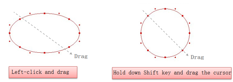
Select several elements of a piece
Allow users to select several elements one time.
Select the Pointer tool
Hold down Shift key, select desired elements(points, segments and so on)
Select the entire piece with just one click
Allow users to select the whole piece by clicking one segment of the piece.
How to do:
Select the Pointer tool
Hold down Alt (Windows) or Option (Macintosh) key, click any segment of the desired piece. Entire piece is selected
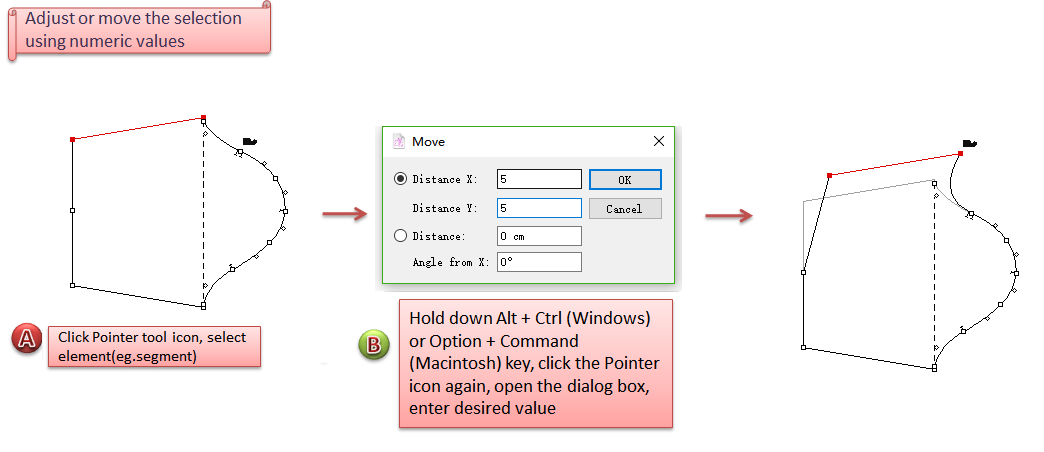
Adjust or move the selection using numeric values
Allow users to move or adjust the piece by entering values
How to do:
Select the Pointer tool
Hold down Alt + Ctrl (Windows) or Option + Command (Macintosh) key, click the Pointer icon, open the dialog box
Enter number, click [OK] button
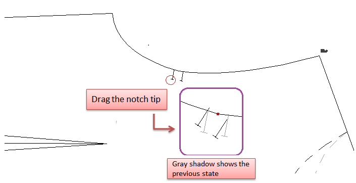
Orient a notch
Allow users to orient a notch by using Pointer tool.
Select the Pointer tool
Click the tip of the notch without releasing mouse button, move the tip to desired notch orientation.
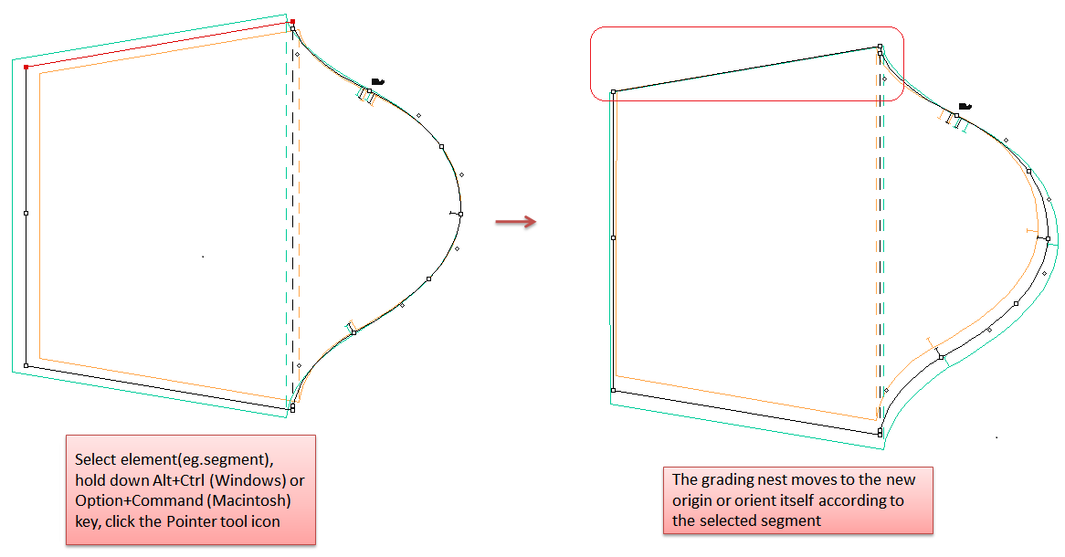
Move the grading nest
Allow users to align the nest to the selected point/segment and check the nest.
elect the Pointer tool
Hold down Alt + Ctrl (Windows) or Option + Command (Macintosh) key, then click the Pointer tool icon
The grading nest moves to the new origin or orient itself according to the selected point/segment
 Zoom In/Out
Enlarge or reduce the view of working area or specific element.
Enlarge or reduce view of working area
Enlarge: Select
Reduce: Select
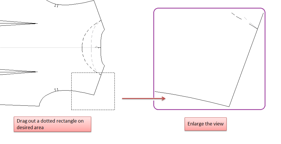
Enlarge or reduce view of a specific section
Allow you to get a closer or farther view of specific part.
How to do:
Select
Release the mouse button, desired part is shown in the central of working area
Note
Allow users to set a zoom level up to a maximum of 2000% and down to a minimum of 0.5%.
Activate Zoom In/Out tool when another tool is selected
Allow user to the pointer can be transformed into the Zoom In / Out tool when another tool is selected.
Activate Zoom In: hold down Ctrl+Shift+Space (Windows/Linux) or Command+Shift+Space (Macintosh) key
Activate Zoom out: hold down Alt+Ctrl+Space (Windows/Linux) or Option+Command+Space (Macintosh) key
or:
Activate Zoom In: hold down Space and roll up the mouse wheel
Activate Zoom Out: hold down Space key and roll down the mouse wheel
 Ruler
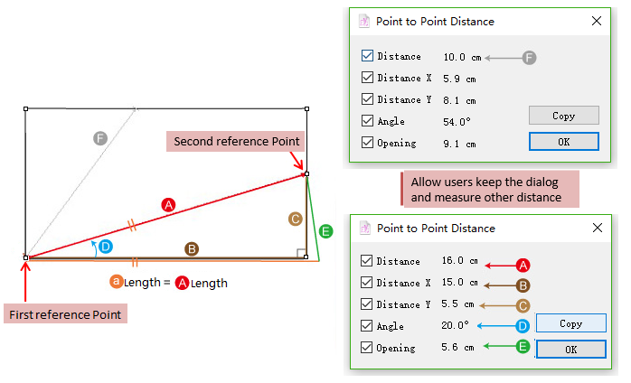
Allow users to measure the distance between two points, or the length of the selected segment.
Measure the distance between two points
Select
Left-click the first reference point and then the second one; or left-click the firsth reference point without releasing the mouse button and drag it to the second one, then release it
The dialog box appears to show the values, allow users to select the desired items
The [Copy] button allow users to copy the values in the dialog box and paste these values into Notepad or another word processing application.
Users can keep the dialogs open and take measure on another piece. Two dialogs appear and allow users to compare the measurement.
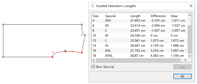
Measure curve length, total length of several segments or the graded segment length
Select the desired element (if several segments are selected, the measurement result is the total length of selected several segments)
Select
Hold down Alt (Windows) or Option (Macintosh) or Alt+Windows (Linux) key, then click working area at random
The dialog box appears, the values are shown as following image (if the segment is not graded, it only shows medium size in the dialog box; if the segment was graded, it shows values of all the sizes in the dialog box)
Users can select and copy the items. If want to make a multiple continuous selection in the list, hold down Shift key, select the first item then click the last one (or drag from first item to the last one); this selects all items in between as well.
To make a discontinuous multiple selection in the list, hold Ctrl (Windows / Linux) or Option (Macintosh) key and click all the sizes you wish to select;
The [Copy] button allows users to copy the values in the dialog box and paste these values into Notepad or another word processing application. And the copied values can be used in grading with Segment Length tool.
Note
For more information about how to use the copied value in piece grading with Segment Length tool, please refer to following introduction section of Segment Length.
 Text
Text
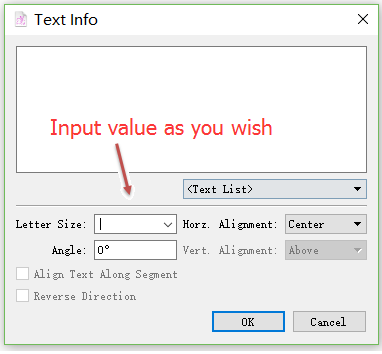
Allow users to write notes on the selected piece or on the working area.
Customize letter size
New in V7.0:
In addition to select the letter size by pulling down the menu, users can also input the size as wish:
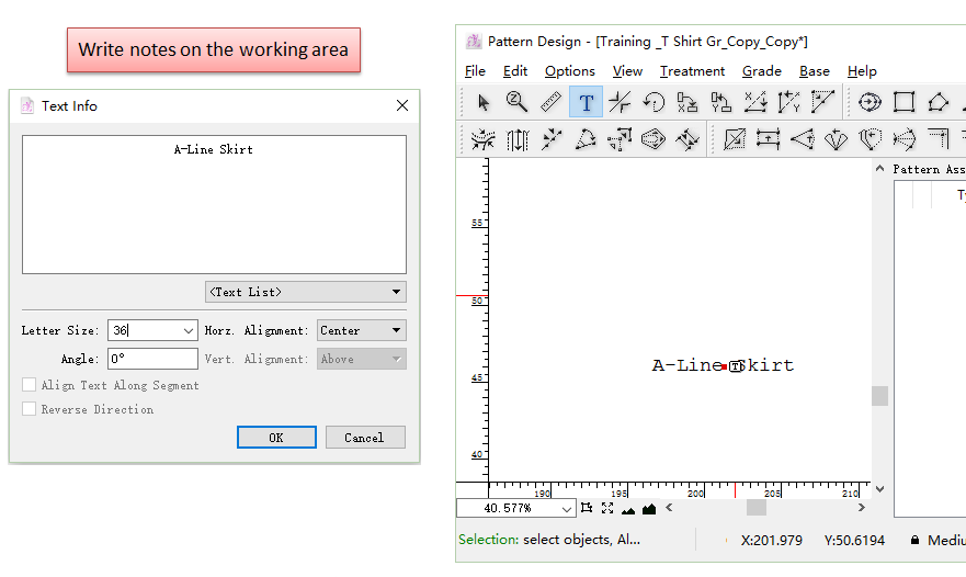
Write notes on the working area
Select
Click the desired text location on the working area, the dialog box appears
Input text, select or input letter size, then click [OK]
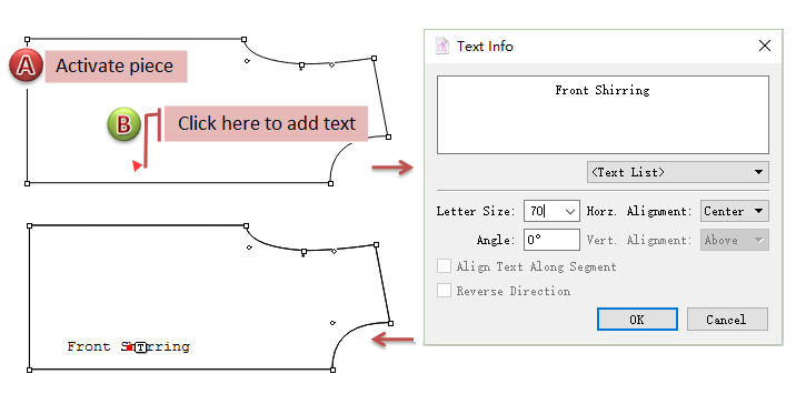
Write notes on the selected piece
Activate the piece
Select
Click the desired location on the piece (e.g. segment), input the text in the dialog box, select or input letter size
Note
If the text is too small to see, keep clicking the “T” to check the text.
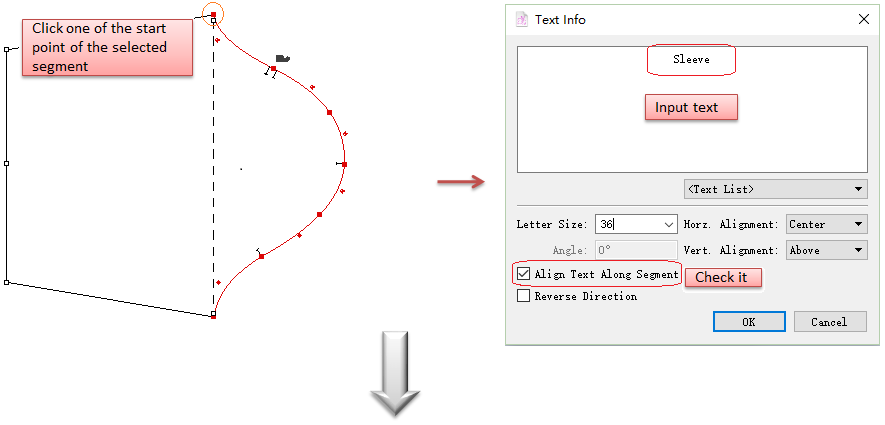
Write notes aligned along the segment
Select the desired segment
Select
Click one of the two start point of the segment to open the dialog box, write the text, and select [Align Text Along Segment] item. After select or input the letter size, click [OK]
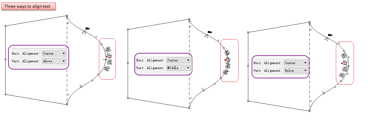
Users can align the text along segment vertically in several ways as desired:
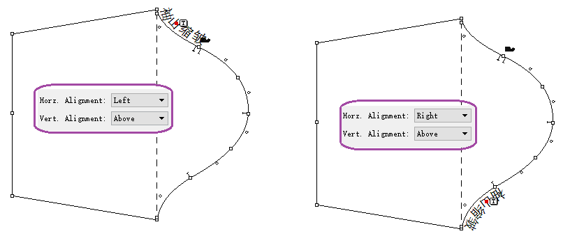
or make text alignment horizontally, like:
Note
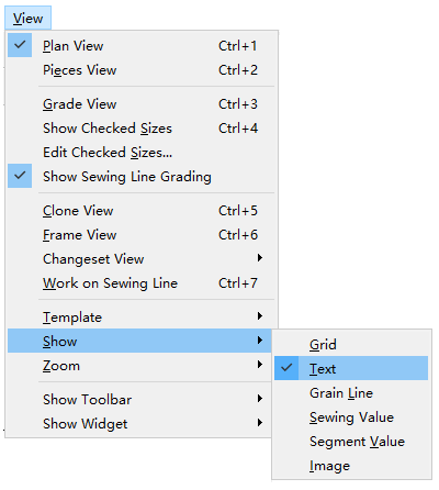
If it only shows the smalltext icon “T” without text, click menu [View] - [Show] - [Text] to show the text.
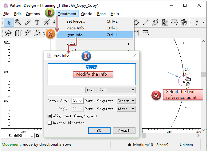
Modify the text
Select the text reference point right next to the text icon
Click Menu [Treatment] - [Item Info…], open [Text Info] dialog box
Modify the information, click [OK]
 Symmetry
Allows users to flip selected element(s) or a complete pattern piece on an axis defined by two reference points.
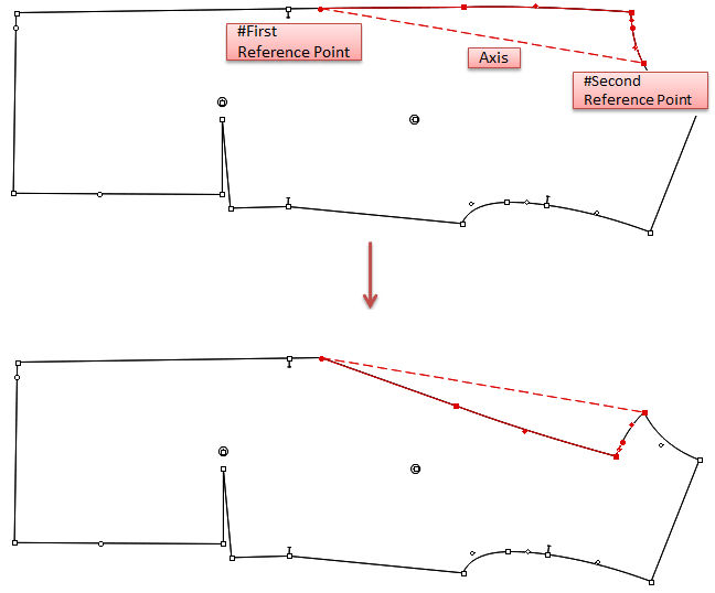
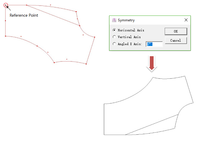
Apply symmetry by two clicks
Select desired element or piece
Select
Click the first reference point
Click the second reference point
Different operation in V7.0:
Select desired element or piece
Select
Click the first reference point. When the cursor is moving, the axis appears and users can preview the flipped result. Dialog appears after the cursor to show the angle info.
Click the second point
Note
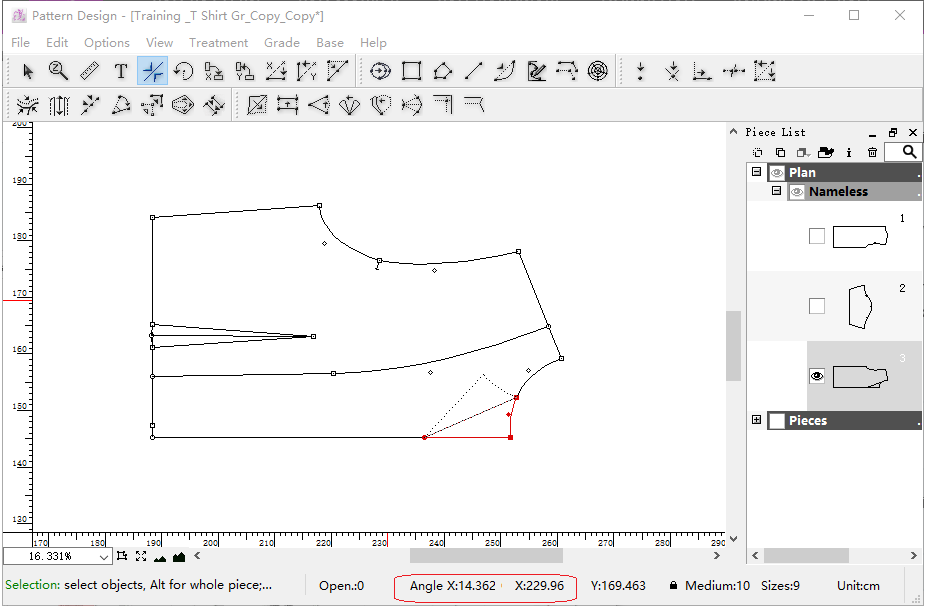
When you hold and move the point, you can view the symmetry angle in the info bar.
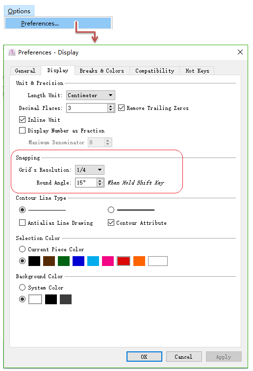
Hold down Shift key (Windows, Macintosh or Linux) if you want to constrain the symmetry axis in either the X or Y axis, or 15°. Define the angle by the setting Round Angle in the [Preference] menu.
Select the Snap to Grid item, in the Options menu, to move elements according to the active grid.
For more information about [Snap to Grid], please refer to the Options menu, select Preference and Display section.
Flip a selection according to a precise axis
V6.0 :
Select desired element or piece
Select
Hold down the Alt (Windows) or Option (Macintosh) or Alt + Windows (Linux) key, and click anywhere on the working area.
Dialog box appears, enter desired value, then click [OK] button
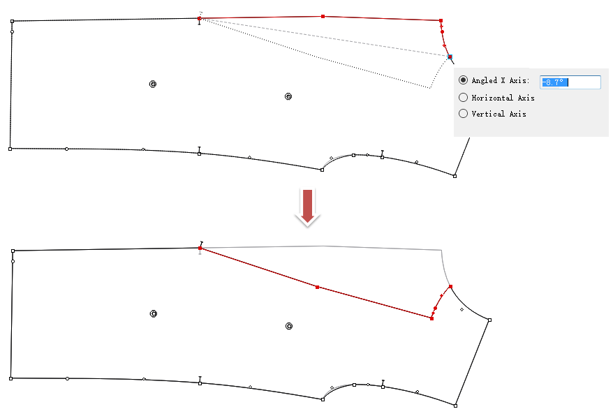
Different operation in V7.0:
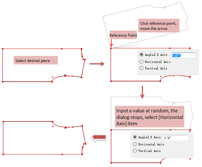
Select desired element or piece
Select
Click the reference point and move the cursor, dialog appears:
Enter angle value, press Enter key on keyboard to confirm
If want to select [Horizontal Axis] or [Vertical Axis] item, enter any value in [Angle] item, then use Tab key to select. Press Enter key to finish operation
 Rotation
Allow users to rotate the selected element or an entire piece.
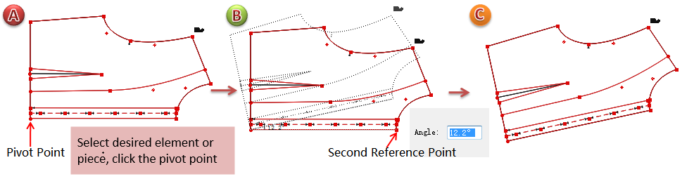
Rotate the selected element or piece
V6.0 :
Select the desired element or piece
Select
Click the first reference point (as the pivot point)
Click the second reference point without releasing the mouse button, a reference dash guideline going from the first point to the second point appears. Those two lines represent an angle.
Pivot the guideline to the desired rotation angle
Note
Hold down Shift key to constrain the rotation angle (every 15°)
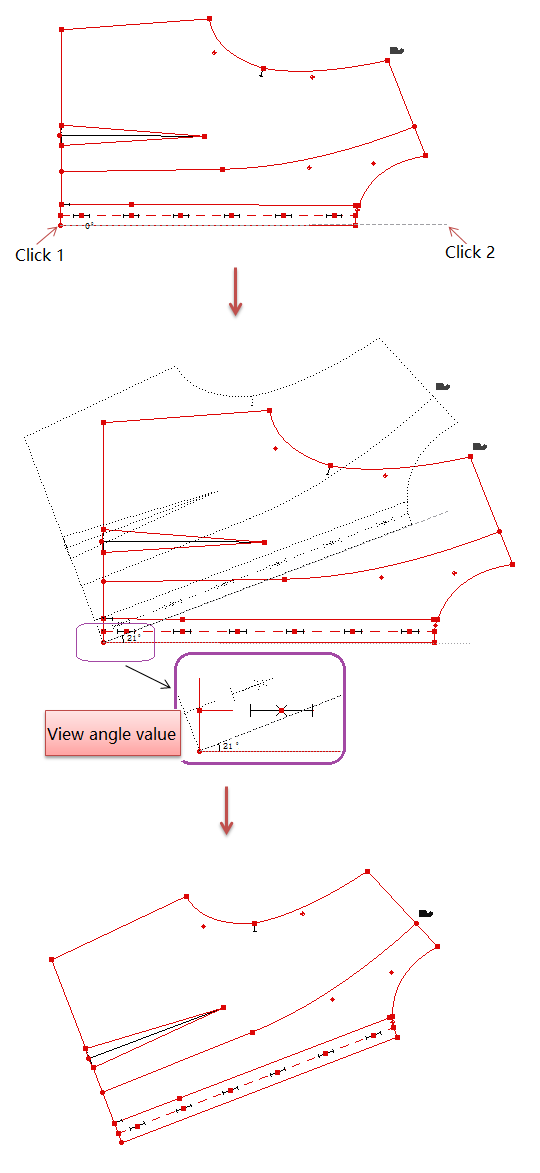
Difference in V7.0:
Select the desired element or piece
Select
Click the first reference point (as the pivot point)
Click the second reference point, move the cursor. Meanwhile, the dialog box appears in the lower-right corner, rotation angle and result are shown
Move the cursor to make desired angle, left-click any where to finish operation
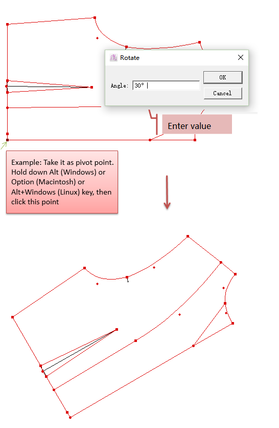
Rotate the selection by entering a precise angle
V6.0 :
Select the desired element or piece
Select
Hold down Alt (Windows) or Option (Macintosh) or Alt + Windows (Linux) key
Click the pivot point to open the dialog box, enter desired angle value, then click [OK] button
Note
Positive value for counter-clockwise rotation while negative value for clockwise rotation.
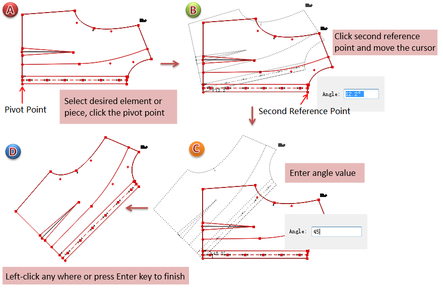
Difference in V7.0:
Select the desired element or piece
Select
Click the pivot point
Click the second reference point, move the cursor. Meanwhile, the dialog box appears in the lower-right corner, rotation angle and result are shown. Enter desired angle value directly
Left-click any where or press Enter key to finish operation
 Orient in X
Allows users to orient the activated piece(s) starting from two reference points on the horizontal axis.
Orient activated elements on the X axis
Activate the element(s)
Select
Click the first reference point
Click the second reference point, the activated element(s) are oriented on a horizontal line according to the reference points

 Orient in Y
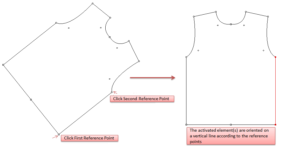
Allows users to orient the activated piece(s) starting from two reference points on the vertical axis.
Orient activated elements on the Y axis
Activate the element(s)
Select
Click the first reference point
Click the second reference point, the activated element(s) are oriented on a vertical line according to the reference points
 Align Two Points in X
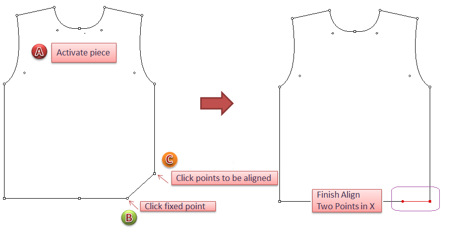
Allows users to align two points or more on the same horizontal axis.
Align two points on the X axis
Activate the piece(s) the two points you want to align are on.
Select
Click the fixed reference point (the second point moves according to a vertical axis for horizontal alignment with the fixed reference point)
Click the point to be aligned
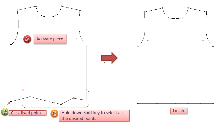
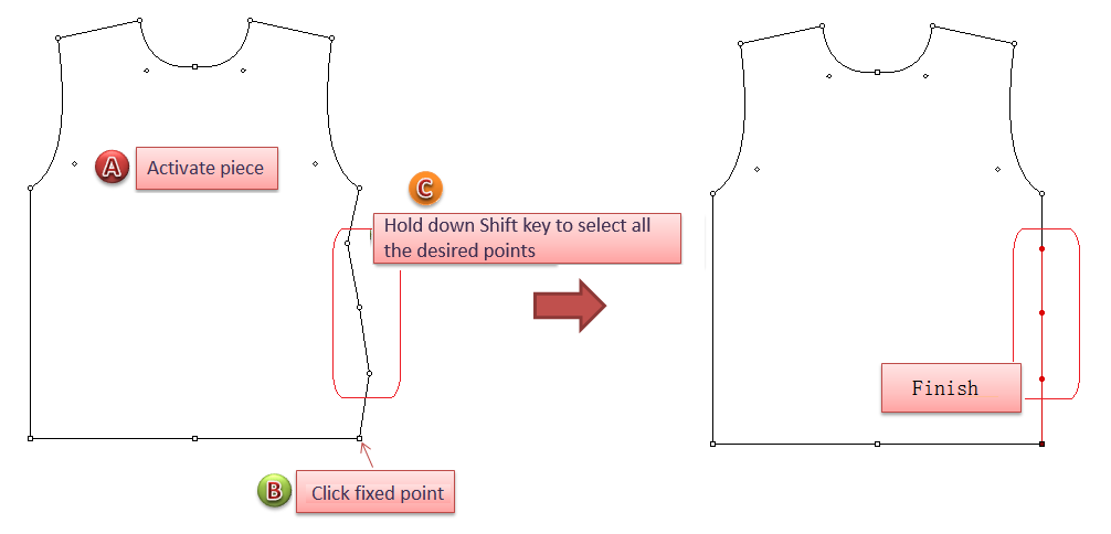
Align many points on the X axis
Activate the piece(s) on which are the points you want to align
Select
Click the fixed reference point (the following points will be aligned according to this point), the cursor turns into a cross
Hold down Shift key, a small + appears near the cross, then click the points one by one
 Align Two Points in Y
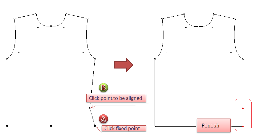
Allows you to align two points or more on the same vertical axis.
Align two points on the Y axis
Activate the piece(s) the two points you want to align are on
Select
Click the fixed reference point
Click the point to be aligned
Align many points on the Y axis
Activate the piece(s) the points you want to align are on
Select
Click the fixed reference point
Hold down Shift key, a small + appears near the cross, then click the points one by one
 Align Points
Allows users to align all the points that are on the selected segment(s) according to two reference points.
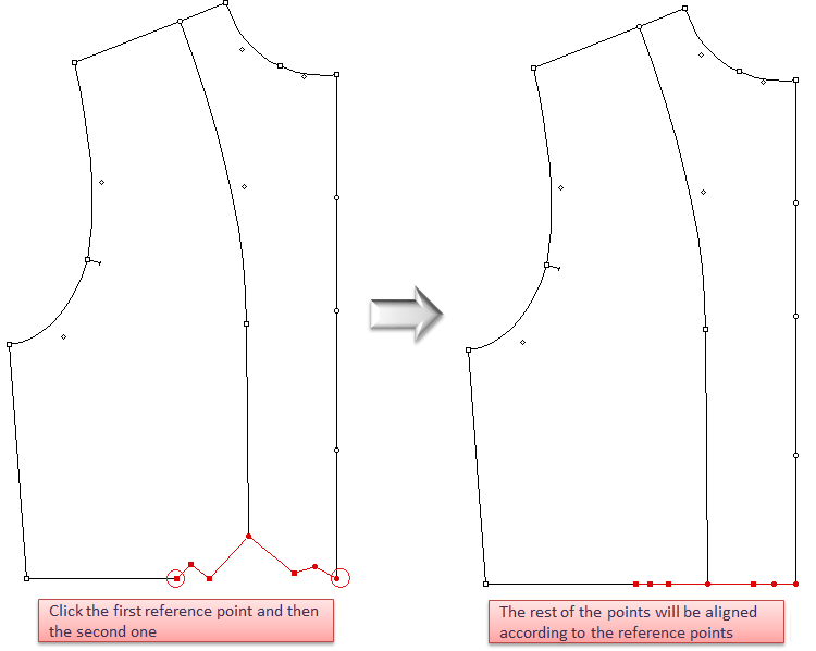
Align points by two clicks
Select the segment(s) the points you want to align are on
Select
Click the first reference point
Click the second reference point
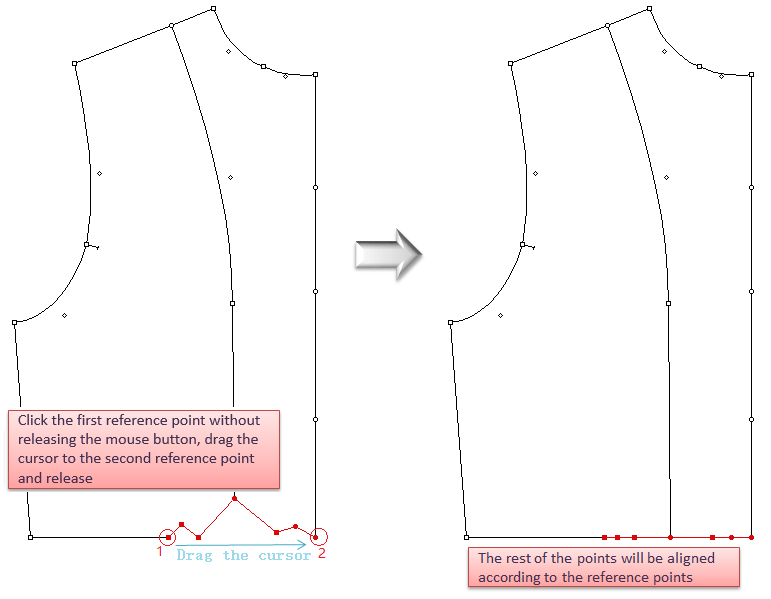
Align points by dragging
Select the segment(s) the points you want to align are on
Select
Click the first reference point without releasing the mouse button, drag the cursor to the second reference point and release the button
 Ellipse / Circle
Allows you to create a circle freehand or according to a precise radius or diameter.
Draw ellipse / circle by free hand
Select
Select
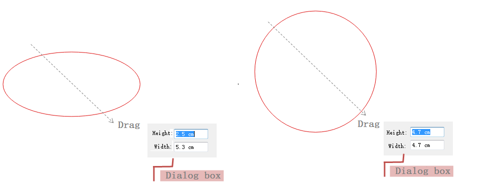
New in V7.0:
The operation to draw shape is the same as above, the difference is that a dialog box is appearing after the cursor, showing the specific value, and allowing to enter new value.
Drwo ellipse/circle by entering value
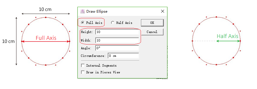
V6.0 :
Select
Hold down Alt (Windows) or Option (Macintosh) key without releasing the mouse button.
A dialog box appears, enter desired value and click [OK] button
For example, draw a circle with a diameter of 10cm:
Note
Internal Segments: select this item to draw the ellipse/circle as internal segment attached to a piece, and its single segment (the segment between two points) can be deleted as it is not closed contour
Draw in Pieces View: The new ellipse/circle appears in Pieces View
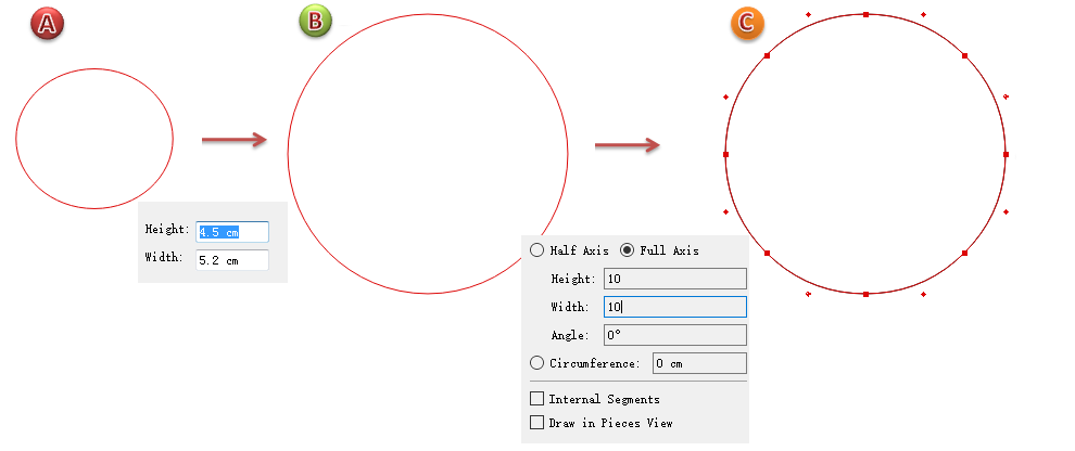
New in V7.0:
For example, draw a circle with a diameter of 10cm:
Select
Left-click the desired location, the dialog box showing values appears after the cursor
Enter 10 in [Height] item, the rest of the items in the dialog box appears, then enter the same value in [Width] item
Left-click any where or press Enter key to finish operation
Note
If the [Full Axis] item was selected before, reselect the [Half Axis], then it will remeber the option made last time.
 Rectangle
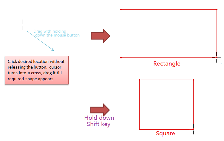
Allows users to create a square or a rectangle freehand or according to precise measurements.
Draw a rectangle freehand
Select
Select
New in V7.0
The operation drawing rectangle is the same as above, the difference is that a dialog box showing values appears after the cursor during the process, and it allows users to enter desired value.
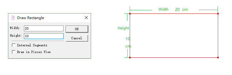
Draw rectangle/square by entering precise value
V6.0 :
Select
Hold down Alt (Windows) or Option (Macintosh) or Alt+Windows (Linux) key, click desired location
Enter value or select option in the dialog box
Click [OK] button
For example: draw a rectangle with a height of 10cm and a width of 20cm.
Note
Internal Segments: select this item to draw the shape as internal segment attached to a piece, and its single segment (the segment between two points) can be deleted as it is not closed contour
Draw in Pieces View: The new shape appears in Pieces View
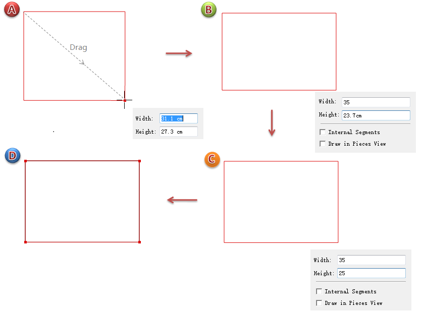
New in V7.0
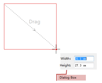
For example, to draw a rectangle with a width of 35cm and height of 25cm.
Select
Left-click the desired position then move the cursor, the dialog showing values appears after the cursor
Enter 35 in [Width] item, the rest of the items appear, enter 25 in [Height]
Left-click any where or press Enter key to finish operation
Note
If want to draw a square, enter the same values in both items, then left-click any where or press Enter key to finish operation.
 Polygon
Allows you to create a polygon freehand.
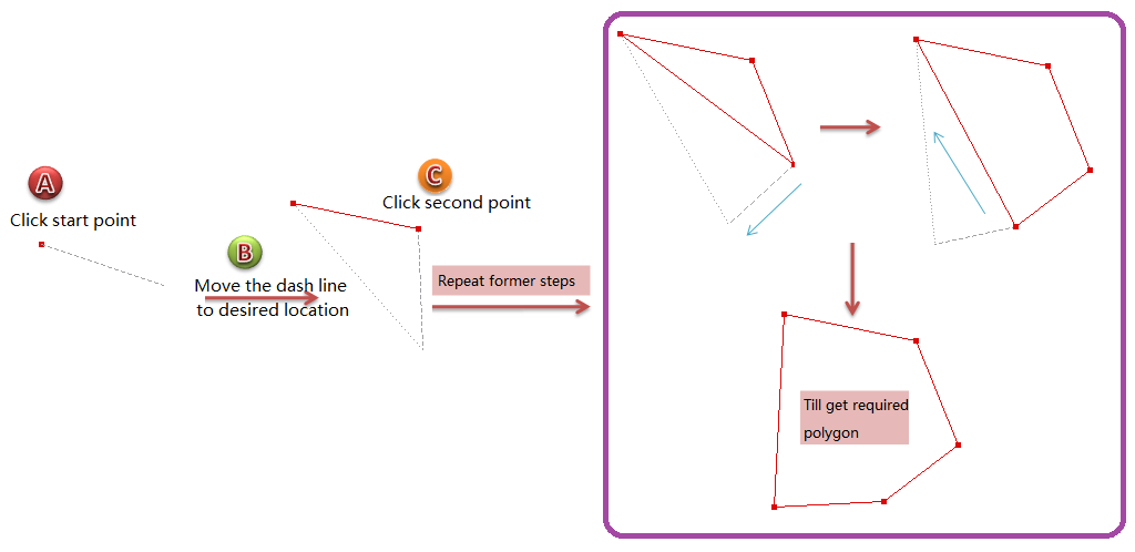
Draw a polygon
Select
Click the starting point, move the cursor, a dash line going from the starting point appears, move it to the desired location and
Click the second point, move the dash line to desired location
Repeat the last step as many times as necessary to get the desired polygon
 Segment
Allows you to draw a segment anywhere on the working area by cursor only or entering precise value.
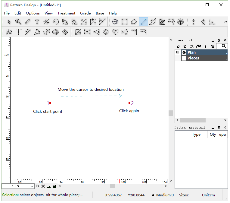
Draw a segment by cursor only
Select
Click the starting point and hold down the left mouse button (Windows / Linux) or the mouse button (Macintosh), drag the cursor to the desired location.
Note
Hold down the Shift key to draw horizontal or vertical segemnt.
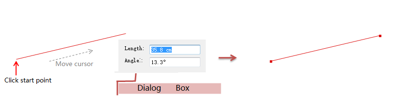
New in V7.0
The steps of drawing segment are the same as that of V6.0, but in V7.0, it shows the specific value in the dialog box following the cursor.
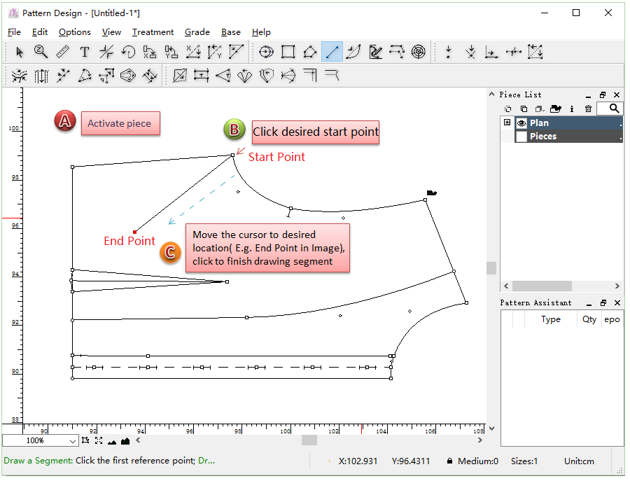
Draw segment on the piece
Activate the piece
Select
Click the desired location on the piece (this point is the start point of the segment), move the cursor to desired location (end point) and click again
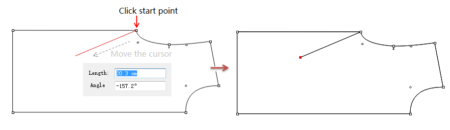
New in V7.0
The steps of drawing segment on the piece are the same as that of V6.0, but in V7.0, it shows the specific value in the dialog box following the cursor.
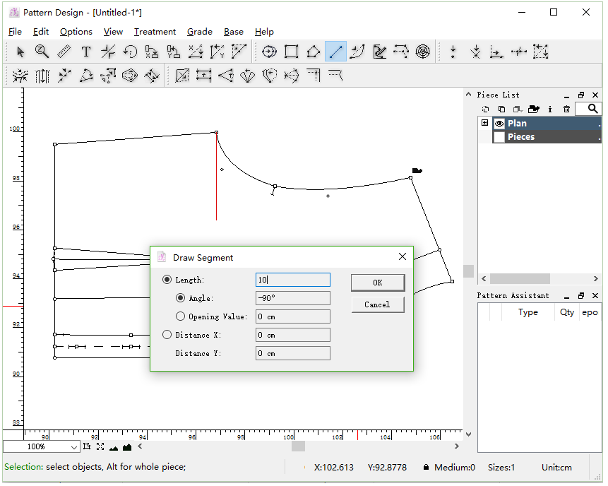
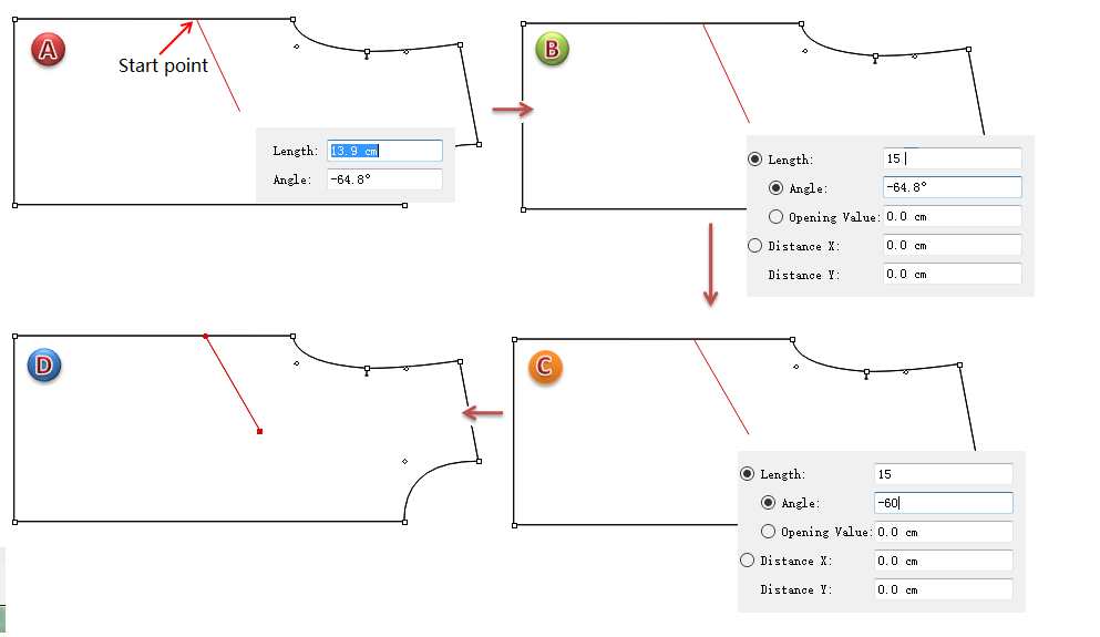
Draw segment by entering desired value
For example, draw a segment attached to the piece, also need to activate the piece at first.
V6.0 :
Select
Hold down Alt (Windows) or Option (Macintosh) or Alt+Windows (Linux) key, click the point as segment’s start
Dialog box appears, enter desired value and click [OK] button
New in V7.0
For example, draw a segment attached to the piece, also need to activate the piece at first.
Select
Click the point as segment’s start, move the cursor, the dialog box showing value appears after the cursor
Enter 15 in [Length] item, meanwhile, the rest of the items appears, then enter values in other items, like -60 in [Angle] item
Left-click any where or press Enter key to finish operation
 Curve
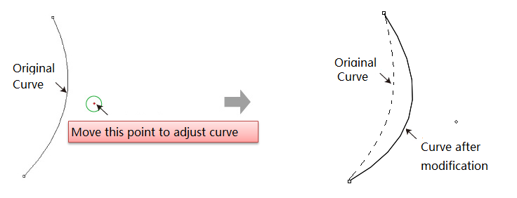
Allow users to create curve by using this tool. Users can draw the curve directly, and do not have to use Segment Tool to draw a segment and then drag it into curve by using Curve Tool; allow users to move a group of control/regular points by entering desired value or by freehand, which improves the efficency of pattern-making.
Draw a curve as desired
Select
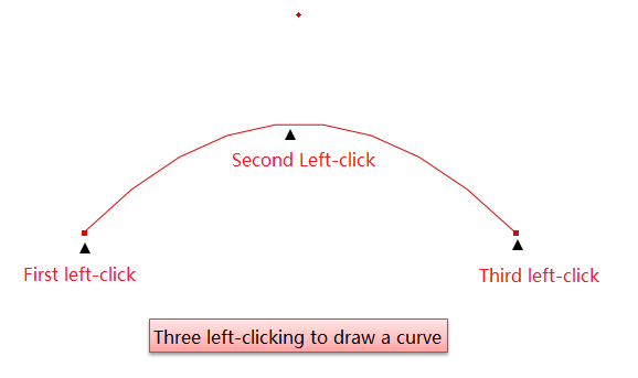
Note
Three points make a curve. Because the limition of points, the curve is not smooth enough, so users can add more points on the curve by using Add Point Tool to adjust the curve.
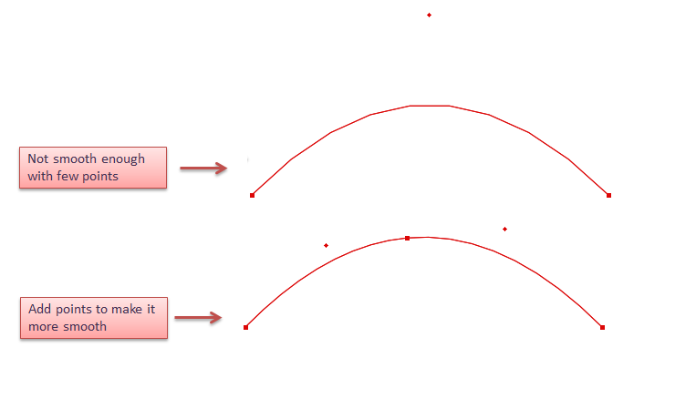
Allow users to move the curve point to modify the bending of the curve.
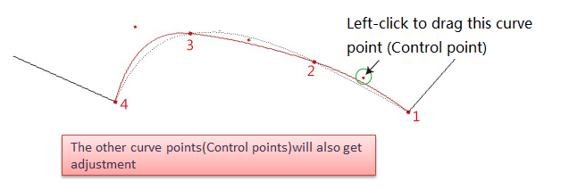
Move a group of curve point (control point) as desired
Select the desired curve;
Select
Left-click one of the curve point without releasing the mouse button, drag the curve to desired area then release the button.
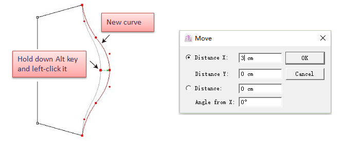
Move a group of curve points (control points) or regular point by entering specific value
Select the desired curve;
Select
Hold down Alt key (Windows) or Option key (Mac), left-click the desired point or segment;
Dialog box appears, enter specific number and click OK.
New in V7.0
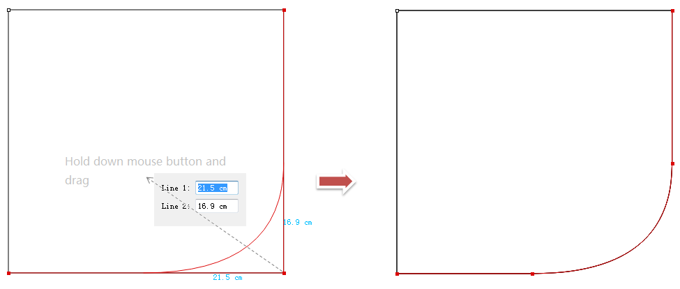
Make rounded corner by dragging or inputting precise value
Turn the angle into rounded corner by dragging or entering number directly.
How to do:
Select two desired segments
Select
Left-click to drag the angle point upwards to make rounded corner, during this process, the values are shown. Allow users to enter desired
Left-click any where to finish operation
 Parallel Line
Allow users to draw parallel line by dragging the cursor, accelerate the efficiency of pattern-making.
Draw parallel line
V6.0 :
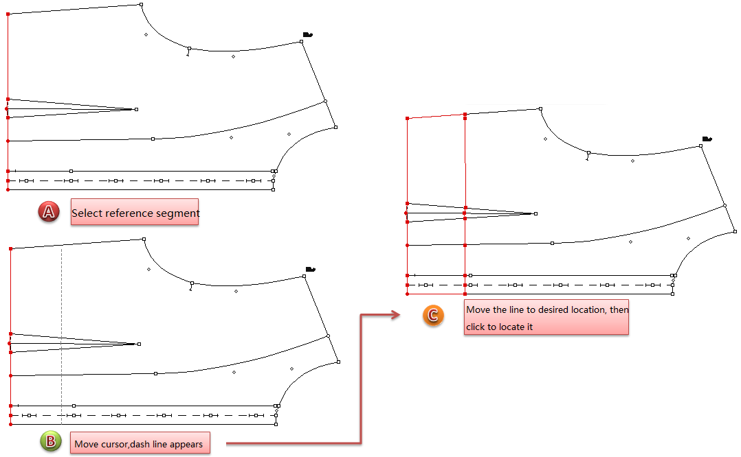
Select the desired reference segment (it can be a segment in the same piece or several segments that are connected, or the contour of a closed piece )
Select
Left-click the reference segment, move the cursor, a dotted line appears (you can see the values on the info bar in the lower-right corner of the window)
Move the dotted line to desired position, left-click to locate it
New in V7.0
The steps of drawing parallel line are the same as above, but in V7.0, it shows the dialog box instantly after the cursor, enable users to check the value, or enter desired value.
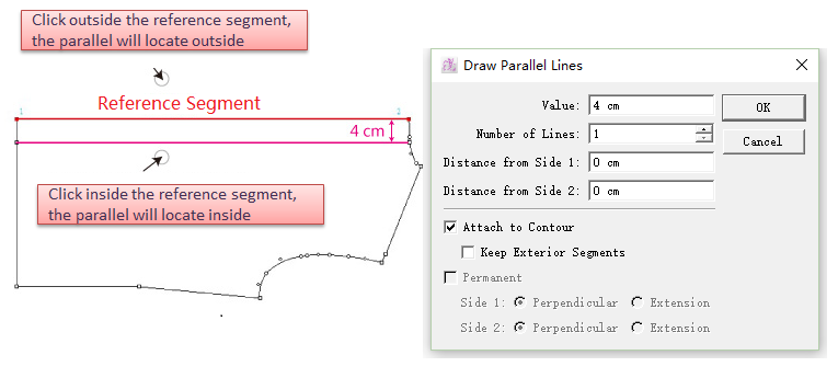
Draw parallel line by entering precise value
V6.0 :
Select the desired reference segment (it can be a segment in the same piece or several segments that are connected, or the contour of a closed piece )
Select
Click either side of the selected segment(s), depending on which side you want the parallel line(s) to be
Enter value, click [OK] button
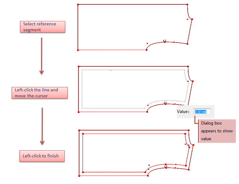
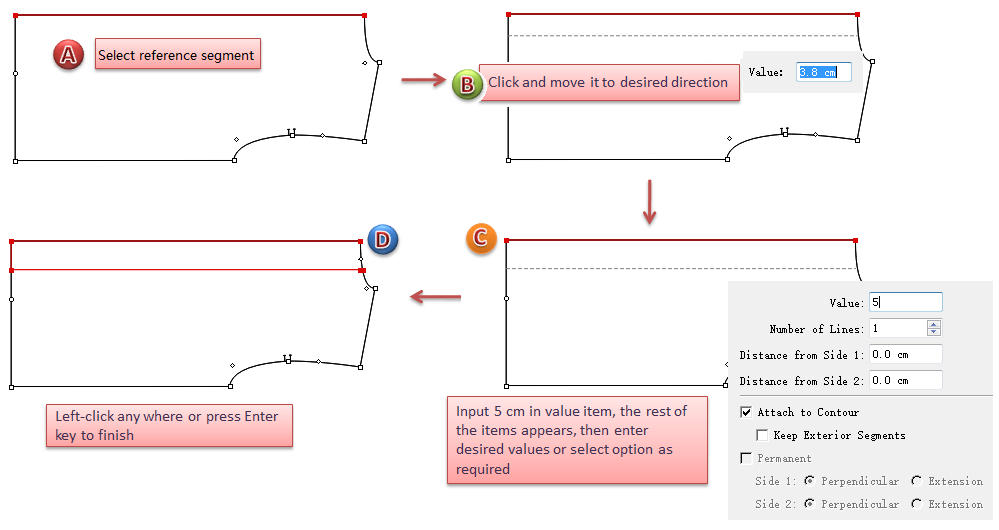
New in V7.0
Select the desired reference segment (it can be a segment in the same piece or several segments that are connected, or the contour of a closed piece )
Select
Left-click the reference segment
Move the segment to desired direction, a dash line that simulates the parallel line appears, and a dialog box showing values appears after the cursor
Enter specific value (e.g.5cm), then the rest of the items appears, enter value or select item as wish
Left-click any where or press Enter key to finish operation
 Ruffle
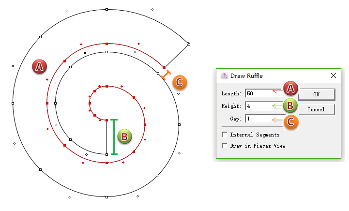
Enable users to make the pattern pieces of ruffle hem or A-line skirt, increase the efficiency and save time.
Draw piece of ruffle hem
V6.0 :
Select
Left-click on the desired location;
Dialog box appears, enter values into it, click [OK].
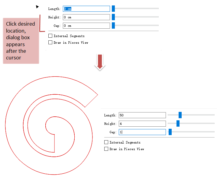
New in V7.0
Select
Left-click desired position, and the dialog appears after the cursor
Enter desired values (use Tab key to move to next item), or drag the slider to modify the ruffle
Left-click any where or press Enter key to finish operation
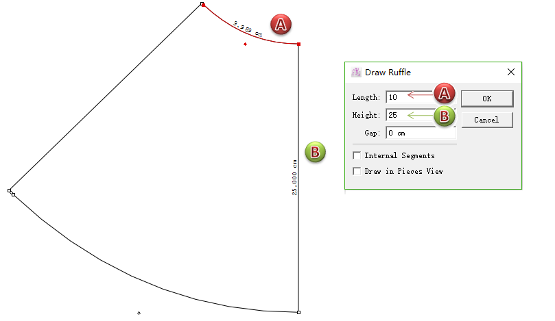
Draw piece of A-line skirt
V6.0 :
Repeat the steps as above.
New in V7.0
Repeat the steps as above:
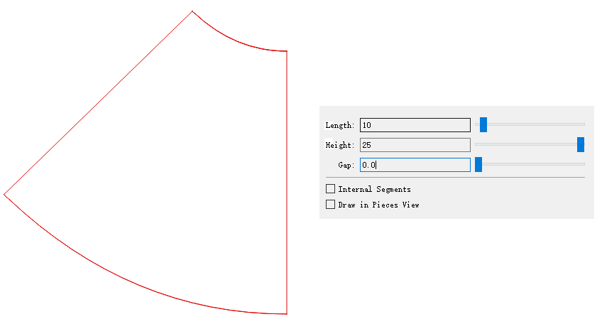
Note
Internal Segments: select this item to draw the shape as internal segment attached to a piece, and its single segment (the segment between two points) can be deleted as it is not closed contour
Draw in Pieces View: The new ruffle appears in Pieces View
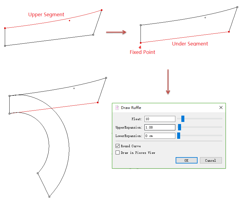
Develop an existing piece(s) into ruffle
New in V7.0
For facilitating users to modify pieces, the feature of
How to do:
Activate the piece and select the upper segment;
Select
Right-click anywhere you wish;
Hold down the Ctrl key (Windows) or Command key (Macintosh) and select the under segment;
Right-click anywhere you wish;
Left-click the fixed point, and input the values or drag the slider to modify the ruffle.
 Create Spline
New in V7.0
The new tool facilitates users to draw a continuous and accurate spline easily and quickly. Create Spline also allows users to curve a straight line or make a parallel without converting other tools.
Draw continuous spline
To draw a continuous spline without point limitation:
How to do:
Select
Draw a spline by continuous left-clicking on the desired area and right-click to finish drawing.
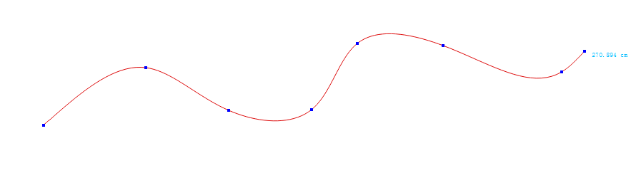
Note
It will be a straight line if just click two points.
How to edit the spline?
Selectr
Right click the spline to show up all the points
Edit the spline:
3.1 Left click the point (keep hold down and do not release it), drag the point to the desired position; or left click to select the point, and then press the arrows on the keybord to move the point.
3.2 Hold down Alt (Windows) or Option (Macintosh) or Alt+Windows (Linux) key, left click the point which you want to move (keep hold down and do not release it), then move the mouse to edit the spline’s shape.
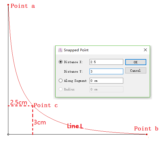
Snap points by exact value
Allow users to snap the curve points by entering precise value.
Draw Line L that goes through Point c
How to do:
Select a reference point (like Point a);
Select
Hold down Alt key (Windows) or Option key (Macintosh) and click on the blank space;
Enter 2.5 to Distance X and 3 to Distance Y, click OK;
Point c appears, then connect Point c and Point b by spline.
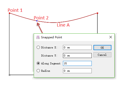
Take Point 1 as reference point, draw Point 2 and the distance between two point along Line A is 3 cm .
Select Line A;
Select
Hold down the Alt key (Windows) or Option key (Macintosh) and left-click Point 1;
Enter 3 cm to Along Segment in the dialog box.
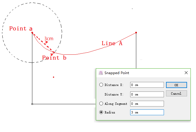
Draw Point b on Line A, and the distance between Point a and Point b is 3 cm:
Select Line A;
Select
Hold down Alt key (Windows) or Option key (Macintosh) and left-click Point a;
Enter 3 to Radius;
Click OK button.
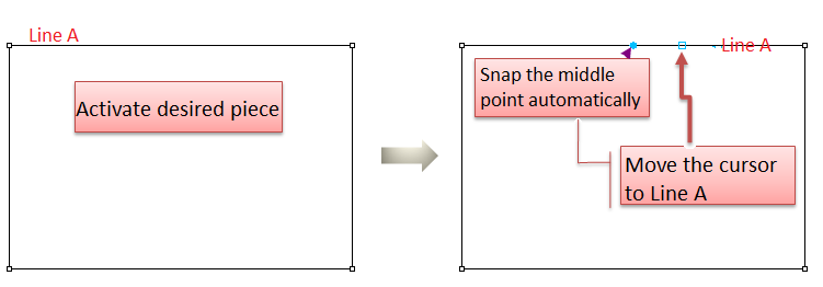
Snap central point
Help users to snap the central point of the selected reference segment.
How to do:
Activate desired piece;
Select
Move the cursor to Line A, the blue point, also the central point of Line A turns up.
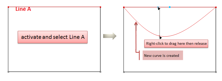
Curve a segment
Right-click to drag the selected straight line into a curve.
How to do:
Activate desired piece, select Line A (your desired segment);
Select
Move your cursor to Line A, right-click to drag it till desired shape.
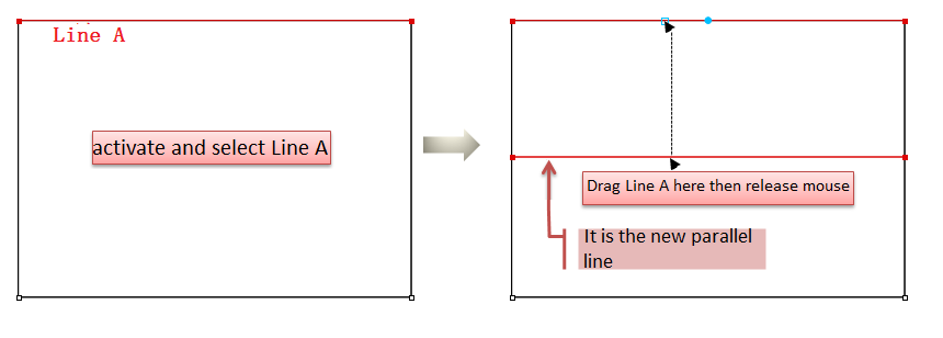
Draw parallel line
Drag the selected spline with left-clicking to draw parallel line.
Activate desired piece, select Line A (your desired segment);
Select
Move your cursor to Line A, left-click to drag it to desired position.
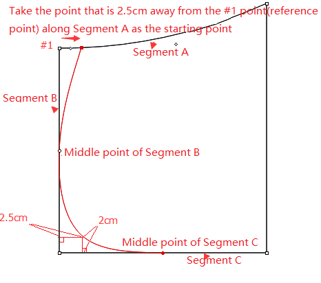
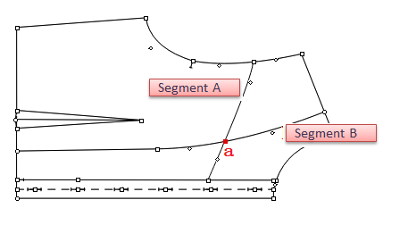
Exercise
For example,
How to do:
Activate the piece and select Segment A;
Select
Hold down the Alt key (Windows) or Option key (Macintosh) and left-click point#1;
Input the values of Along Segment in the dialog box, a point will appear in Segment A and left-click it;
Move the mouse to line B, it will snap the middle point of Segment B automatically;
Left-click the middle point of Segment B;
Hold down the Alt key (Windows) or Option key (Macintosh) and left-click the point#2, input values in Distance X and Distance Y, the point will appear, then left-click it;
Move the mouse to line C, the middle point of Segment B will appear automatically, then left-click it;
Right-click to end drawing.
Note
Press Z key on the keyboard to undo the former point;
Left-click to add point with holding down the Shift key. Left-click to select the point wanted to be deleted with holding down the Ctrl key (Windows) or Command key (Macintosh) then press the Backspace key on the keyboard;
If users want to modify the shape of the existing spline, select Create Spline tool, then right-click the spline. The points appear so drag them to modify.
 Point
Allows you to add a point on a piece or within the working area where the click is made.
Add a point
Select
Click the desired location.
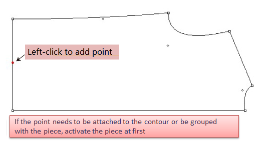
Note
To add a point to a piece, activate the piece at first.
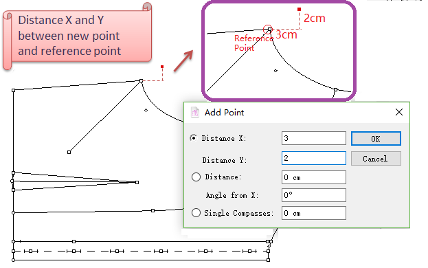
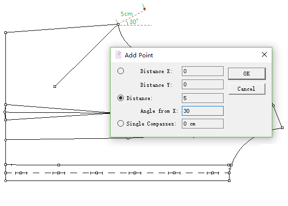
Add a point by entering precise value
V6.0 :
Activate the piece;
Select
Hold down Alt (Windows) or Option (Macintosh) or Alt+Windows (Linux) key, left-click a reference point (point with the coordinates 0, 0);
Open the Point dialog box, enter value, and click [OK] button.
New in V7.0
Activate the piece;
Select
Left-click the reference point, the dialog box appears instantly after the cursor;
Enter desired value, like entering 1 in [Distance X] item, then the rest of the items appears. Enter values in desired items;
Left-click any where or press Enter key to finish operation
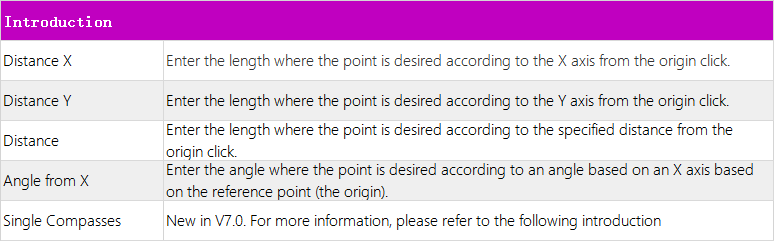
Single Compasses
New in V7.0
Taking a point as reference, users can add a new point on the desired segment with specific length. The distance between that two points is the specific value the user input in Single Compasses dialog box.
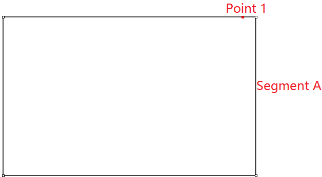
For example: now we are going to draw a segment intersects Segment A at the new point Point 2. And the length of the segment (between Point 1 and Point 2) is 15 cm.
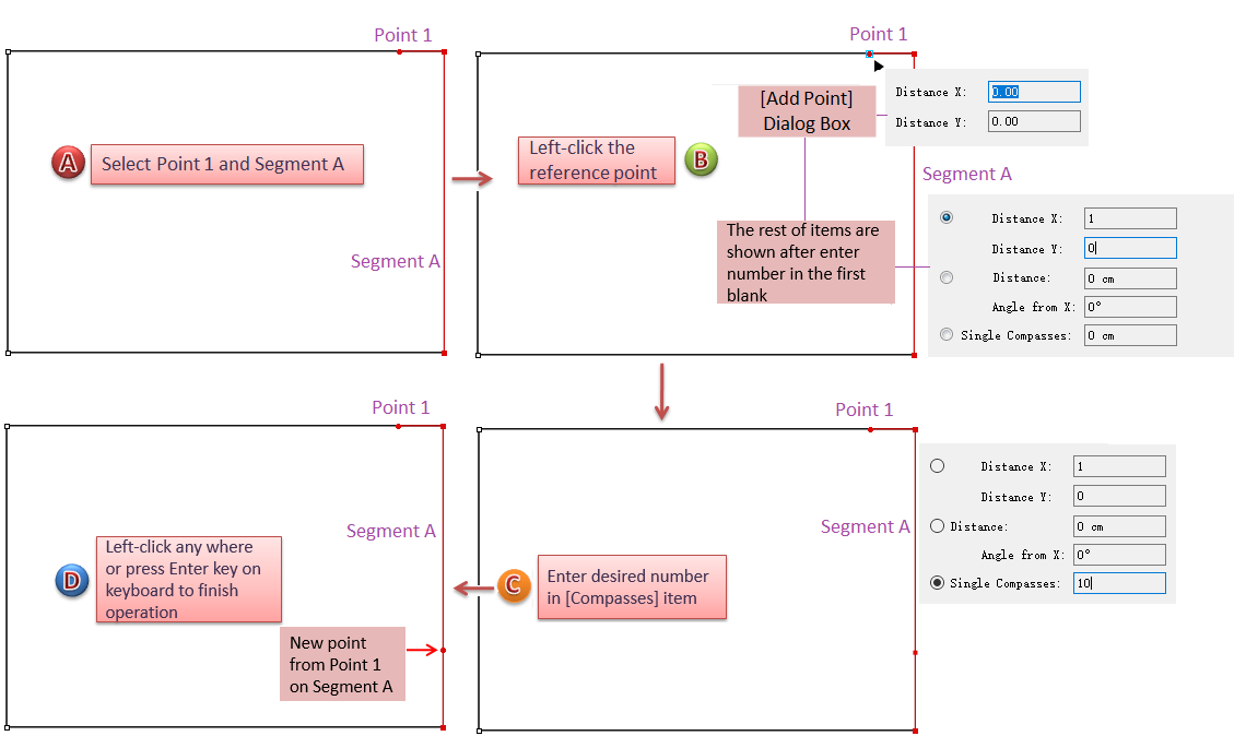
How to do:
Select Point 1 and Segment A;
Select
Click Reference Point 1, the dialog box appears lower-right corner of the cursor. Enter value in Distance X, the rest of items are shown;
Enter value 10 in [Compasses] (as the default unit is cm, it works even though enter number without unit)
Left-click any where or press Enter key on your keyboard to finish operation.
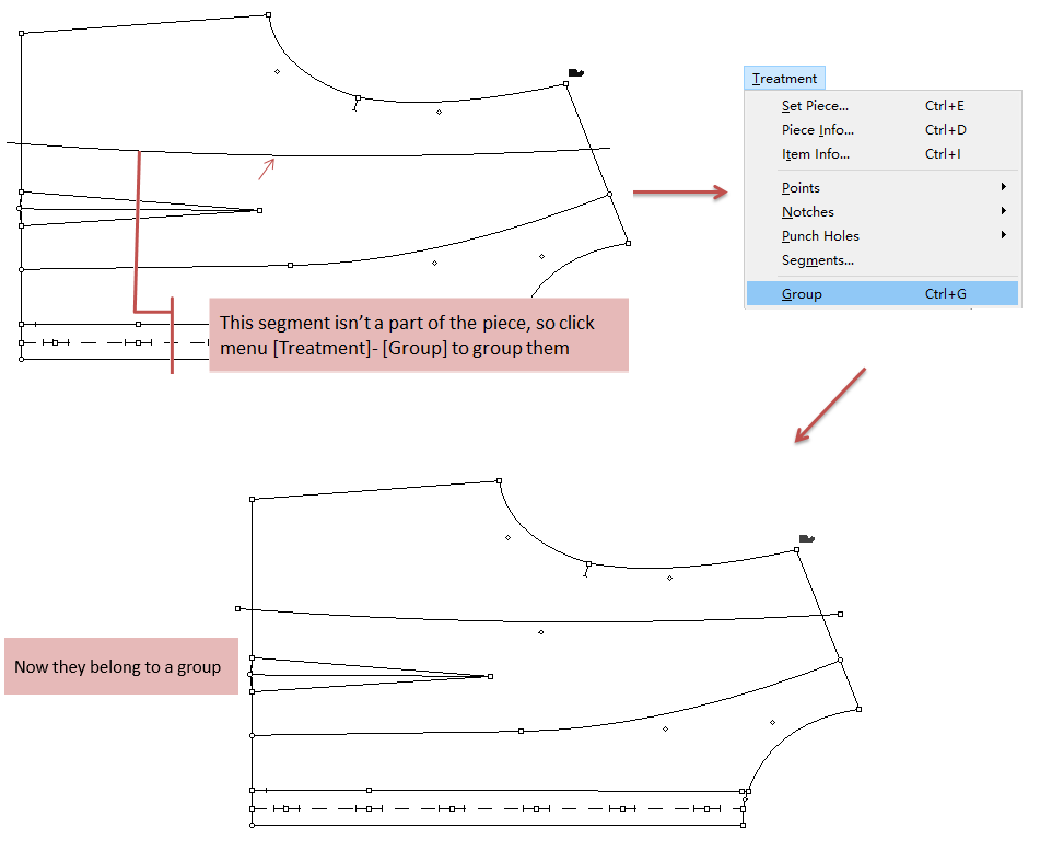
 Attach Segments
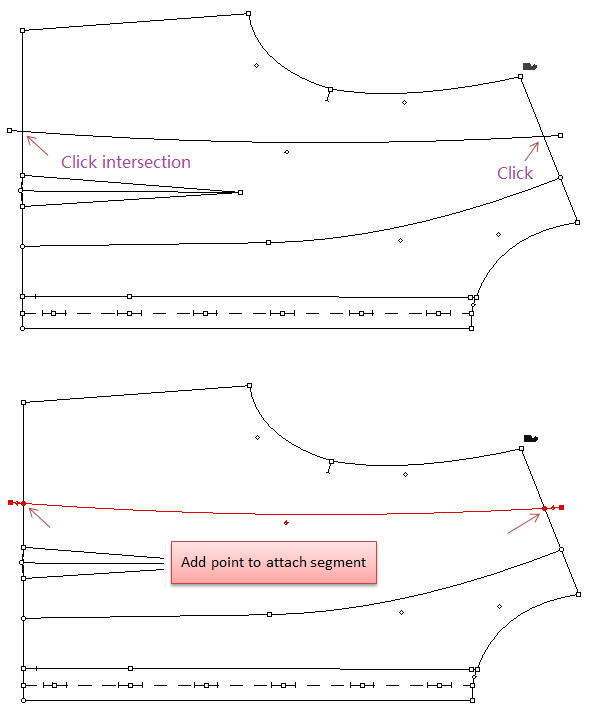
Allows users to add a point on an intersection between two lines or to merge two points one on top of the other; or break the point on the internal cross lines (new in V7.0). To attach segments, the elements users intend to merge must be part of the same group, otherwise, users need to make them a group.
Attach two segments
Activate the piece which the segments are on, or select the intersecting segments;
Note
Select
Click the intersection
Break point
New in V7.0
Allow users to break the point on the cross lines (internal lines only). It helps users combine or break point more easily, accelerate the efficiency of making patterns.
How to do:
Activate the desired piece;
Select
Hold down the Shift key, left-click the intersection point;
The following picture shows the result. Use Pointer tool
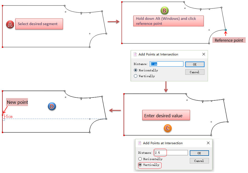
 Add Point to Segment
Allow users to add point to segment.
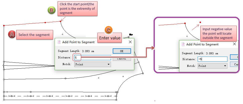
How to add point to segment
Add point to the segment of single size/Medium size
Select the desired segment;
Select
Click the start point (must be one of the extremities of the segment);
The [Add Point to Segment] dialog box appears, enter desired value and click [OK] button.
Note
Enter a positive value, the point is located on the segment; enter a negative value, the point is located outside the segment.
Add point to the segment of all sizes
Select the desired segment of medium size;
Select
Hold down the Alt (Windows) or Option (Macintosh) or Alt+Windows (Linux) key, the cursor becomes a cross, left-click the start point (must be one of the extremities of the segment);
Input the desired values in the dialog box, and click [OK] button:
Note
Often used for adding notches in right position.
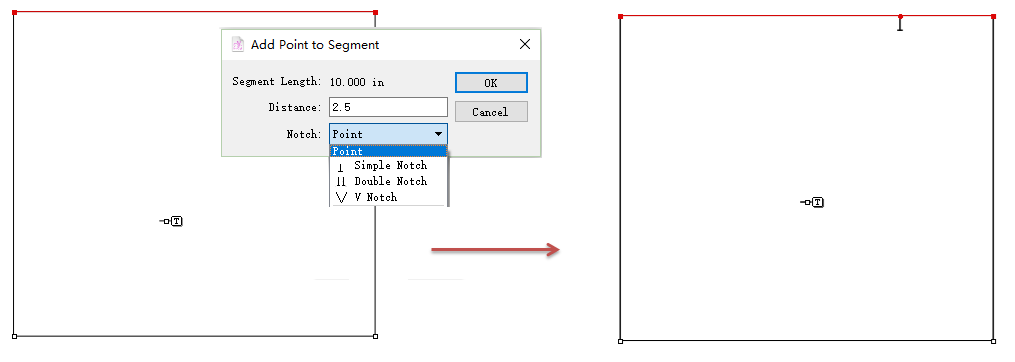
Add a notch while add a point
New in V7.0
Notch option is added to the dialog box, users can add a point and a notch at the same time:
 Divide Segment
Allows users to divide a segment into several parts equally.
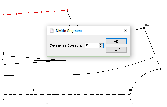
Divide a segment
Select the segment.
Select the Divide Segment tool.
Click the segment, the [Division Segment] dialog box opens, enter the desired quantity of division.
Note
The number of divisions is up to 1000.
 Intersection Points
Allows users to add points on selected segments that are aligned from a projection guideline.
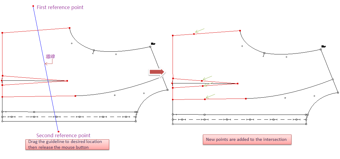
Add points
Select the segment(s) where points are required;
Select
Click the desired location of the first reference point, then click the desired location of the second reference point, hold down the left mouse button (Windows / Linux) or the mouse button (Macintosh), a guideline appears;
drag it to the desired location, release the mouse button;
Points appear on all the selected segments intersecting the guideline.
Add points on selected segment(s) with precise value
Select the segment(s) where points are desired.
Select
Hold down the**Alt** (Windows) or Option (Macintosh) or Alt +Windows (Linux) key, the arrow turns into a cross, then click the reference point;
The dialog box appears, enter at which distance from the reference point you want to add a point and select the radio button for the required axis (horizontal or vertical).
Note
In V7.0, allow users to previews the result when enter the value.
 Segment Sync
Simulate to close the dart(s) / shirring, or merge the pieces together, and to adjust the contour as desired by using this tool.
Note
Before using this tool, recommend the users to enable the Shadow function, so that uesrs can check and compare the results.
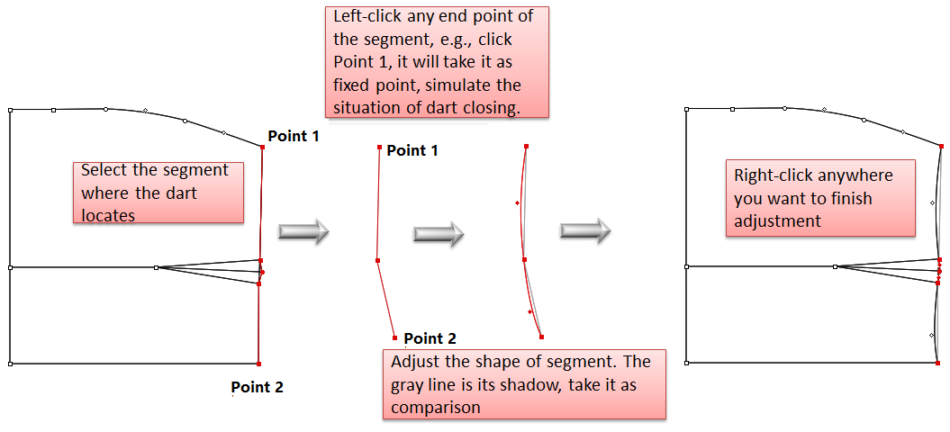
Simulate dart closing, modify the segment
Select desired element (the segment where the dart locates);
Select
Left-click any endpoint of the segment (the one you click is the fixed point);
Now it shows the state of dart closing, you can modify the segment by dragging it; (if the piece is too small to modify, press the Space key on your keyboard and roll the mouse wheel to enlarge the view)
Note
Modify it in two ways:
Left-click the desired point and drag it to the position you wish, release the button; or left-click the segment without releasing the button, drag it to a curve directly.
Select the desired point, modify it by using the arrow keys on your keyboard.
Modify the segment. Right-click to finish modification.
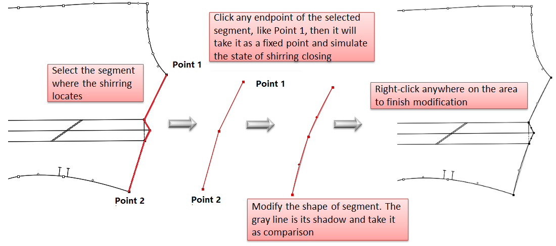
Simulate shirring closing, modify the segment
Select desired element (the segment where the shirring locates);
Select
Left-click any endpoint of the segment (the one you click is the fixed point);
Now it shows the state of shirring closing, you can modify the segment by dragging it; (if the piece is too small to modify, press the Space key on your keyboard and roll the mouse wheel to enlarge the view)
Note
Modify it in two ways:
Left-click the desired point and drag it to the position you wish, release the button; or left-click the segment without releasing the button, drag it to a curve directly.
Select the desired point, modify it by using the arrow keys on your keyboard.
Modify the segment. Right-click to finish modification.
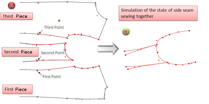
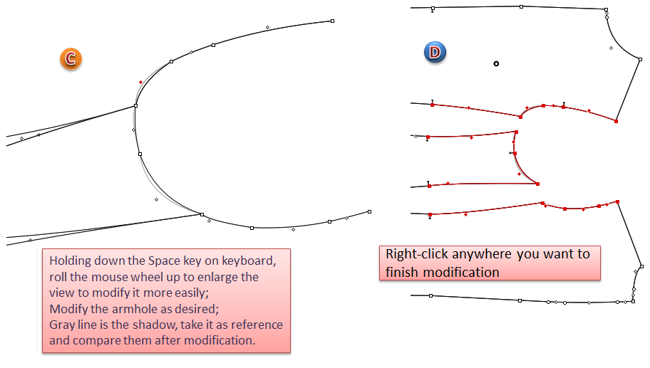
Simulate pieces sewing, modify the segment
For example, simulate to sew the pieces together, modify the shape of armhole.
Select the desired segment;
Select
Left-click the first point (the point on the first section), the second point (the one on the second section), and the third point one by one;
Now it shows the state of side seams sewing together, you can modify the shape of armhole by dragging it (if the piece is too small to modify, press the Space key on your keyboard and roll the mouse wheel to enlarge the view);
Note
Modify it in two ways:
Left-click the desired point and drag it to the position you wish, release the button; or left-click the segment without releasing the button, drag it to a curve directly.
Select the desired point, modify it by using the arrow keys on your keyboard.
Modify the shape of armhole. Right-click to finish modification.
 Walking Piece
It shows the measurements of the segments and calculates the difference between segments; and allow users to modify the measurements as desired.
Note
For comparing the results easily, select [Shadow] function.
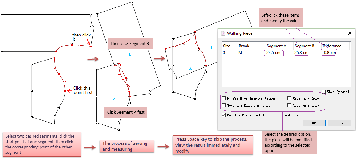
View if lengths of two segments are same
Select two desired segments;
Select
Left-click one of the start point (as the fixed point) of the segment (as Segment A), then click another start point of the segment (as Segment B)
It simulates the process of sewing (press Space key to skip this process)
Dialog box appears, allows users to view or change the values, or select desired items, then click [OK] to confirm.
Note
Modify the value of Segment A, the change will apply on the Segment A (first-click segment)
Modify the value of Segment B, the change will apply on te Segment B (second-click segment)
Modify the value of Difference, the change will apply on the Segment B (second-click segment)
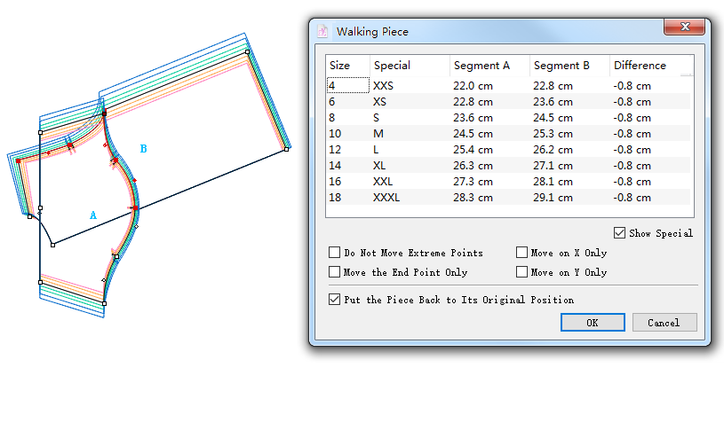
View if lengths of two segments are same on the grading pieces
Select two desired segments;
Select
Hold down Alt (Windows) or Option (Macintosh) or Alt+Windows (Linux) key, the cursor turns to a cross, left-click one of the start point (as the fixed point) of the segment (as Segment A), then click another start point of the segment (as Segment B)
It simulates the process of sewing (press Space key to skip this process)
Dialog box appears, allows users to view or change the values, or select desired items, then click [OK] to confirm.
 Segment Length
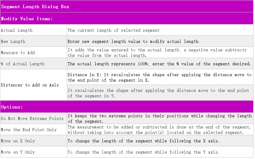
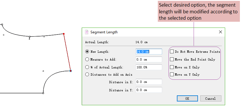
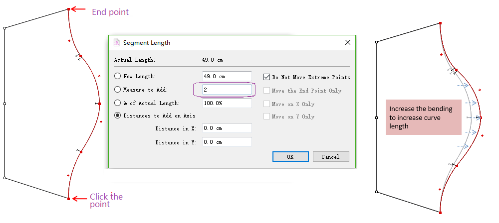
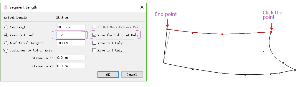
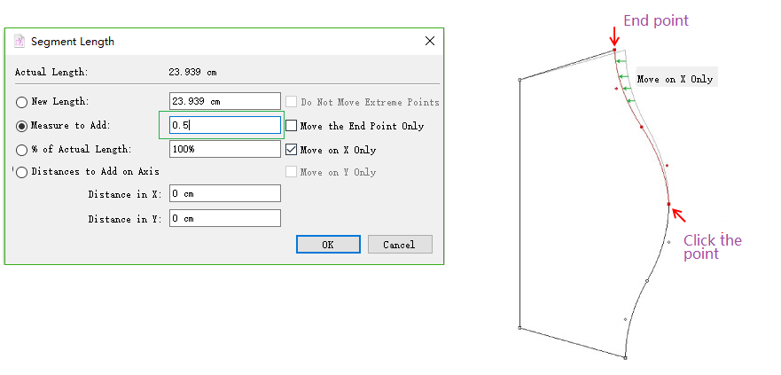
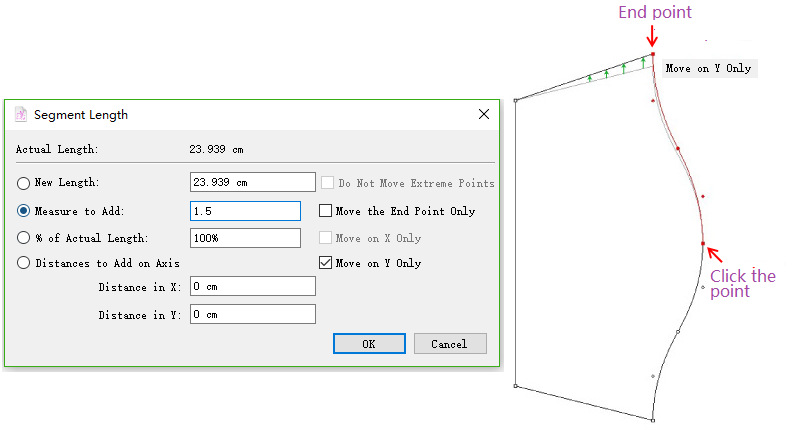
Allows users to obtain or modify information about the length of the selected segment(s).
View or modify the length of selected segment
Select the desired segment(s);
Select
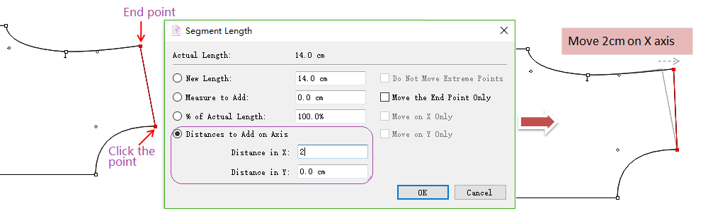
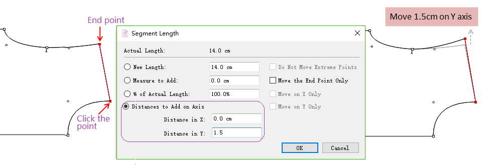
Click one of the extremities of selected segment (takes this point as fixed start point, then the other is end point)
Dialog box opens, enter desired value or select option (if no option is selected, the added measurement is added proportionally to the entire segment), then click [OK]
Example
Distance to add on axis:
Distance in X
Distance in Y
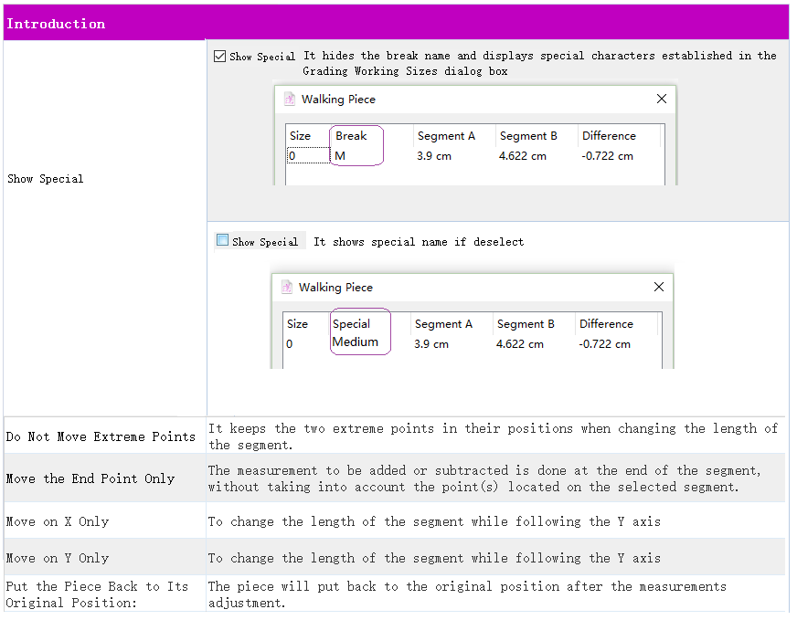
Do not move extreme points:
Move the end point only:
Move on X only:
Move on Y only:
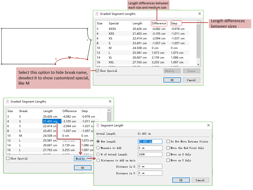
View or modify the graded segment lengths
Select the desired segment
Hold down Alt (Windows) or Option (Macintosh) or Alt+Windows (Linux) key, click one of the extremities on the segment (first-click point as fixed start point, the other is end point)
Click the fixed point where the measurement starts. The point must be at the extremity of a segment. The Graded Segment Lengths dialog box appears. It displays the measurements of all sizes, double-click to select the size(s) to be modified, or click the value and click [Modify] button to change it;
After modification, click [OK] button.
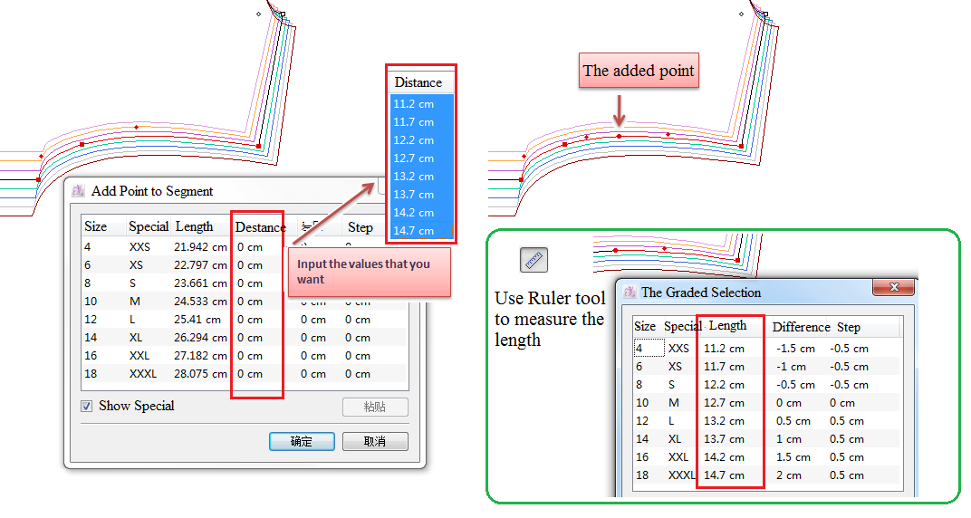
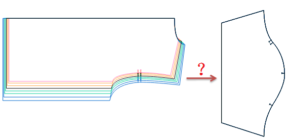
Length Segment tool works with Ruler
For example:
The bodice piece is graded. Now copy the graded value of the armhole to the one without grading:
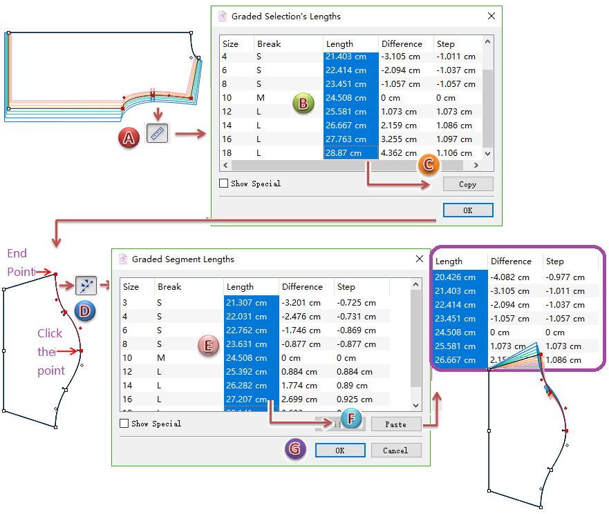
Steps:
Measure the armholes lengths of all sizes by using
The dialog box appears, select the values of corresponding items ([Length]/[Difference]/[Step]), like selecting all the values under [Length] item;
Click [Copy] button, then close the dialog box;
Measure the back sleeve cap line by using
The dialog box appears, select values of all sizes under [Length] item (according to the former copied items);
Click [Paste] button, then click [OK].
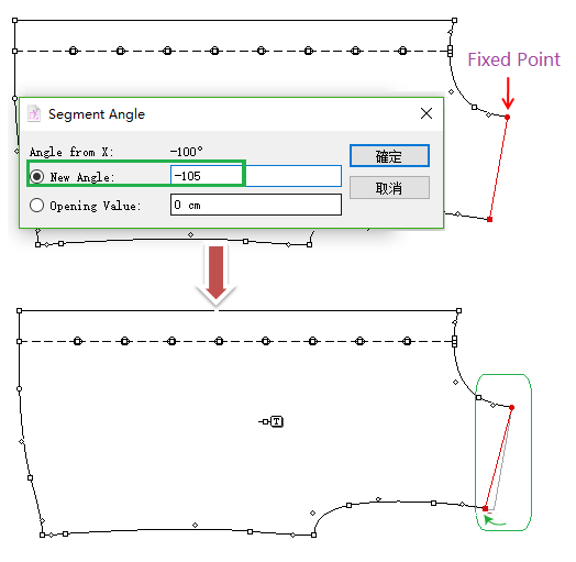
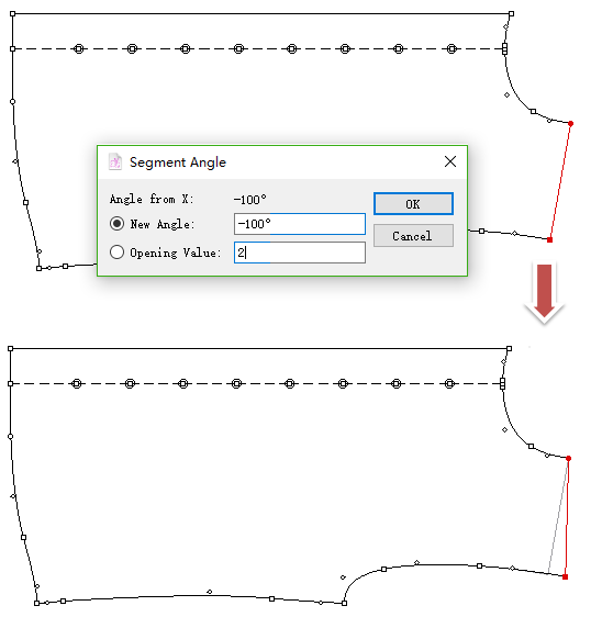
 Segment Angle
Allows users to read the angle of a segment and change it to a precise angle, if necessary.
Obtain or modify information for a Segment Angle
Select desired segment;
Select
Click the fixed point (must be one of the extremities of the segment);
Enter value in the dialog box, then click [OK].
Example of New Angle option:
Example of Opening Value option:
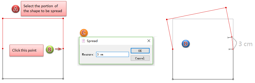
Spread a piece
Select the desired part;
Select
Hold down Alt (Windows)or Option (Macintosh)or Alt+Windows (Linux) key;
Click the point to be spread (Opening side), the dialog box appears;
Enter value and click [OK] button.
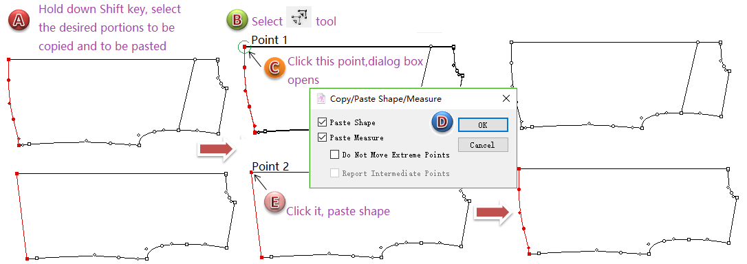
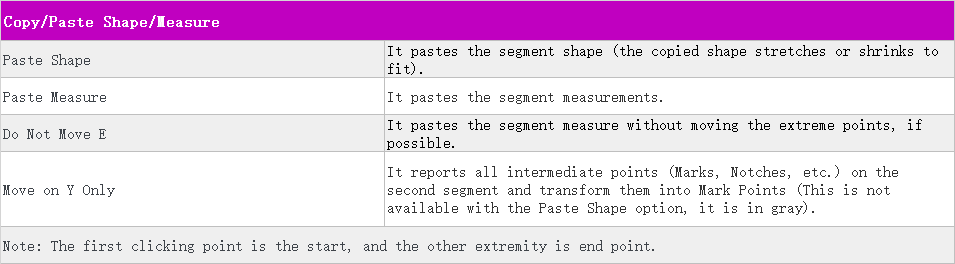
 Copy/Paste Shape/Measure
Allows users to copy the shape and/or measure of a segment and paste it over another segment.
Copy/Paste Shape/Measure
Hold down Shift key to select the elements you wish to copy;
Note
Two segments must be from the different shapes.
Select
Click the starting point of the segment to be copied (Point 1);
Select desired options and click [OK] button;
Click the starting point of the shape to be pasted upon (Point 2).
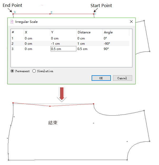
 Irregular Scale
Allow users to reshape a piece on selected points, which improve the efficency of pattern-making.
How to do:
Select a segment with at least 3 points;
Select
Click the first point, then the last point (it will sort the points according to the first point and last point)
Enter desired value in dialog box, then click [OK].
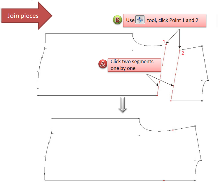
 Join/Split Shapes
Allow users to join two different shapes; or split one shape into two pieces.
Join shapes
Select two segments need to join together;
Select
Click the fixed point of the first shape and the one of second shape (hold down Shift key to save the style line)
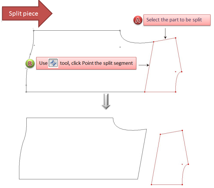
Split a shape
Select the style line and all the segments that are on on side of the shape need to be split (must be a closed contour);
Select
Click on the style line.
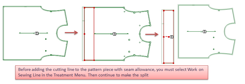
Split the pattern piece with seam allowance
New in V7.0
Allow users to split the pattern piece with seam allowance.
 Mirror
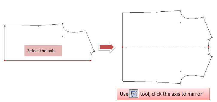
Mirror a piece
Select the axis of reflextion of the piece wish to reflect;
Select
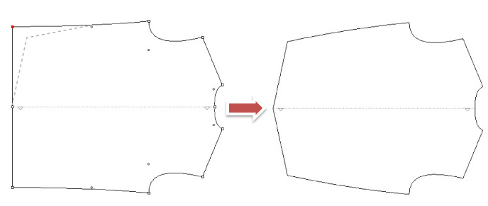
Click the selected segment (axis), it unfolds into a complete piece;
If you don’t remove the axis, one side change and another side also change;
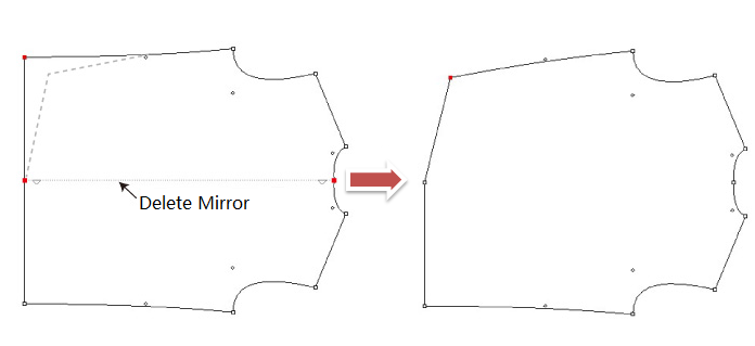
If remove it, one side change but another doesn’t change;
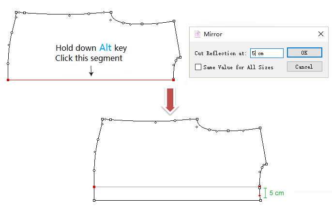
Mirror a piece and cut the reflection at a defined width
Select the axis;
Select
Hold down Alt (Windows) or Option (Macintosh) or Alt+Windows (Linux) key, click the axis, dialog box appears. Enter value and click [OK] button.
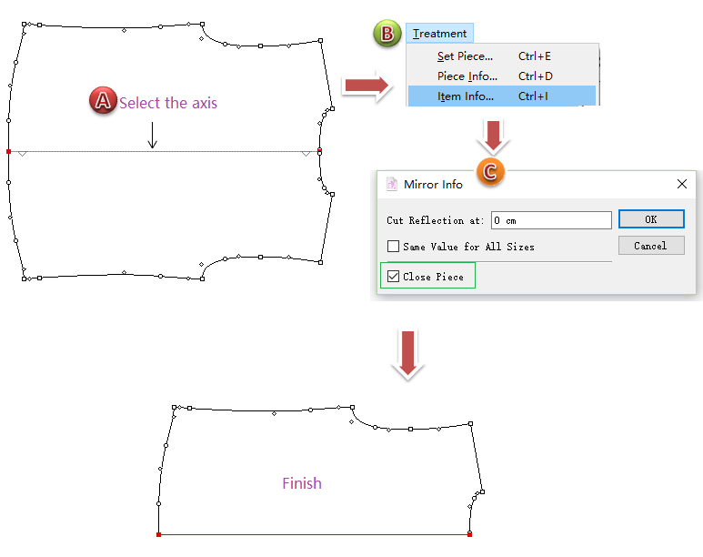
Close mirror
Select the axis;
Select Menu [Treatment] - [Item Info];
The dialog box appears;
Select [Close Piece] option, then click [OK] button
 Pleat
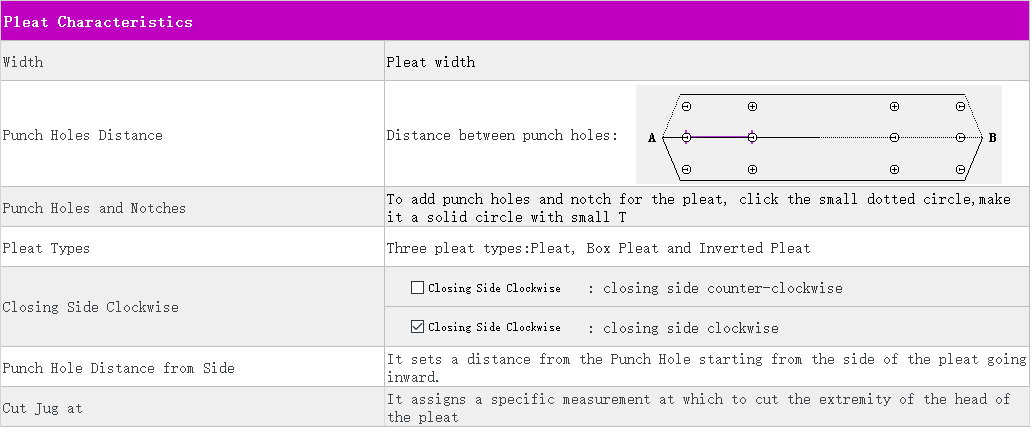
Allow users to develop a pleat on a piece.
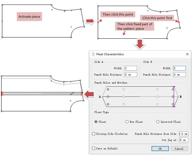
Develop a pleat
Activate the piece;
Select
Click the first reference point (A), then click the second reference point (B), click the fixed part of the piece;
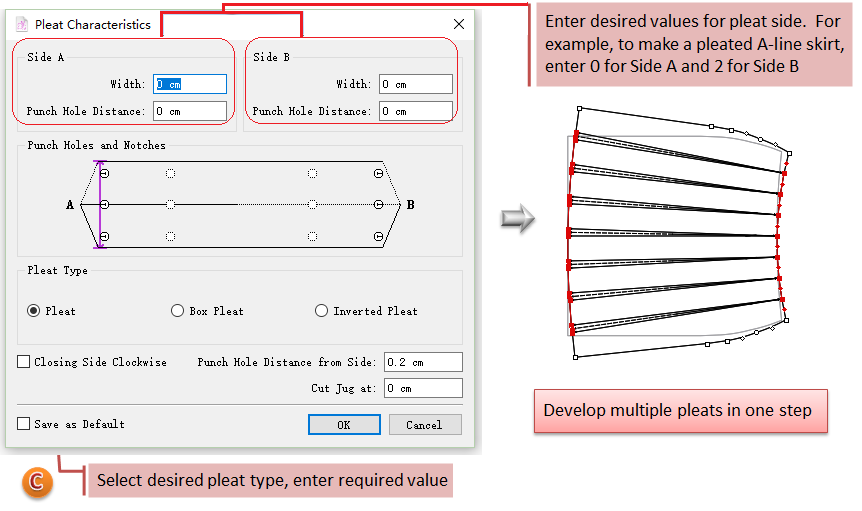
The dialog box appears, select pleat type, enter values, and click the punch holes and notches (if necessary), then click [OK] button.
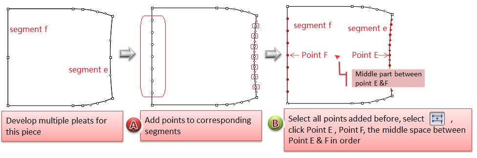
Develop mutliple pleats in one step
Add points to segments (Segment e & Segment f), for example, if you want to develop 7 pleats, then add 7 points on each segment;
Select all new-added points, then select
Click a point (E.g. Point E) on Segment e, then click corresponding Point F on segment f;
Note
The click point is fixed point, the pleats will develop according to it.
The dialog box appears, select pleat type, enter values, and click the punch holes and notches (if necessary), then click [OK] button.
Note
Allow value 0 in the Width of Side A but not in the Width of Side B. So if develop a pleat with one side of value 0, note the order of clicking: first click is Pleat A, and second click is Pleat B.
 Dart
Dart
Allow users to create a dart within a shape from its contour.
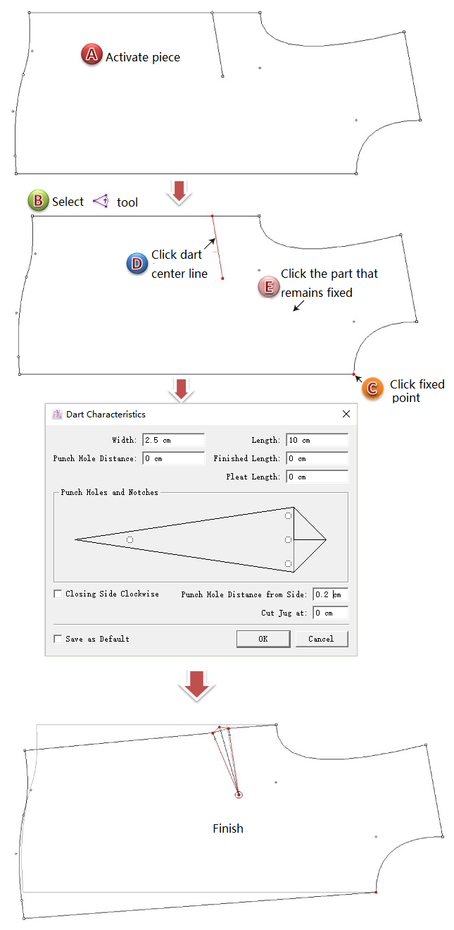
Develop a dart
Activate the piece;
Select
Click the fixed point, then click the segment indicating the position of the dart, and then click the part of the piece that remains fixed;
The dialog box appears, enter desired value and click [OK] button.
Add a dart without spread the piece
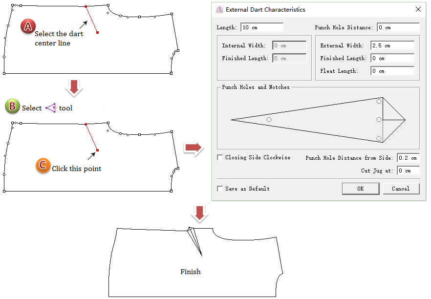
First way: draw a segment and add a dart
Draw a segment on desired location, it is the central line of the new dart;
Select the segment;
Select
Click the start point;
Dialog box appears and enter value, click [OK].
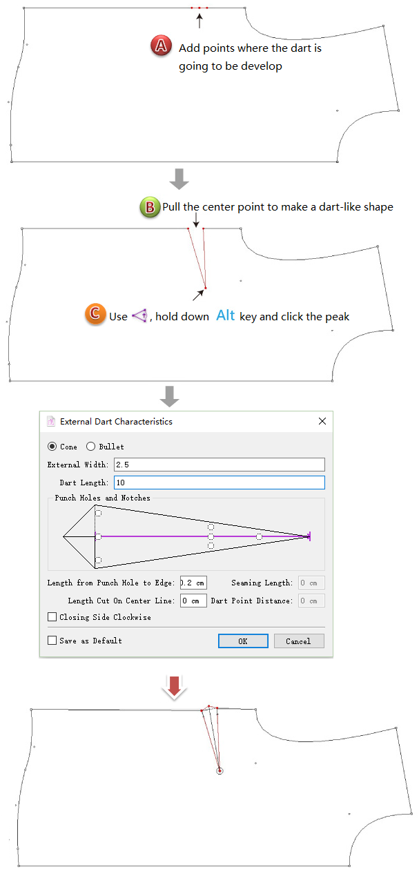
Second way: make a dart-shaped opening and then add a dart
Add points to desired location, then drag out dart-shaped opening;
Select
Hold down Option (Mac) or Alt (Windows) key, click the tip;
Dialog box appears and enter value, click [OK].
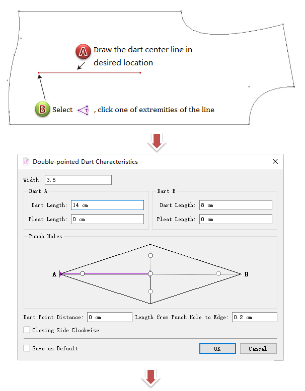
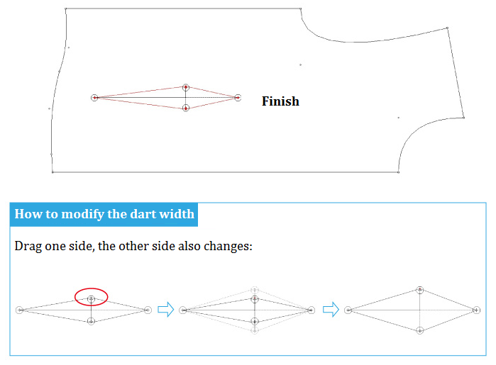
Make double-pointed dart
Draw a segment on desired location;
Select
Click a start point (A);
Enter value in the dialog box, click [OK].
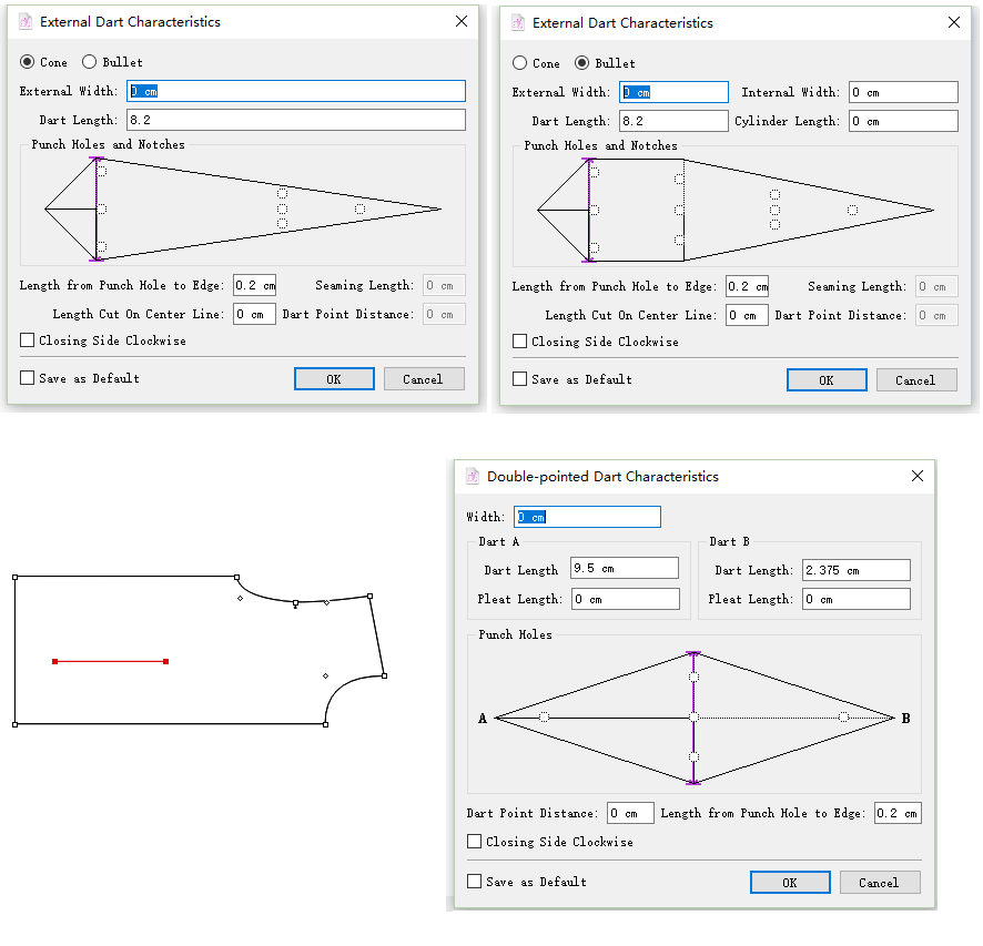
Rearrange the content in dart dialog box
New in V7.0
We sort out the darts in the dialog box: Cone, Bullet, Double-pointed Dart, make it more simple to check; the corresponding position of the dart will be highlighted in purple when enter the value.
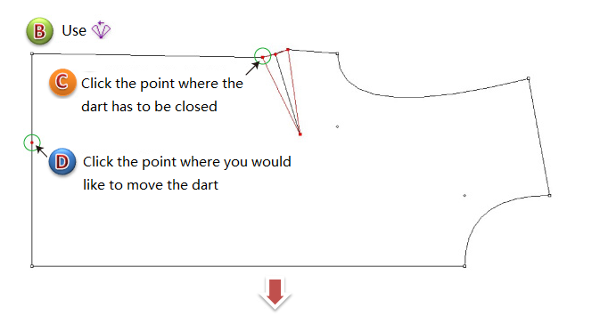
 Dart Pivot
Allow users to pivot a dart to a new location.
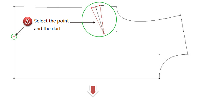
Pivot a dart
Add a point to desired location where you would like to move the dart;
Select the point and the original dart;
Select
Click the point where the original dart has to be closed, then click the point where you would like to move the dart;
Enter value and click [OK].
Note
The dart will move to the side according the clicking point in 4th step.
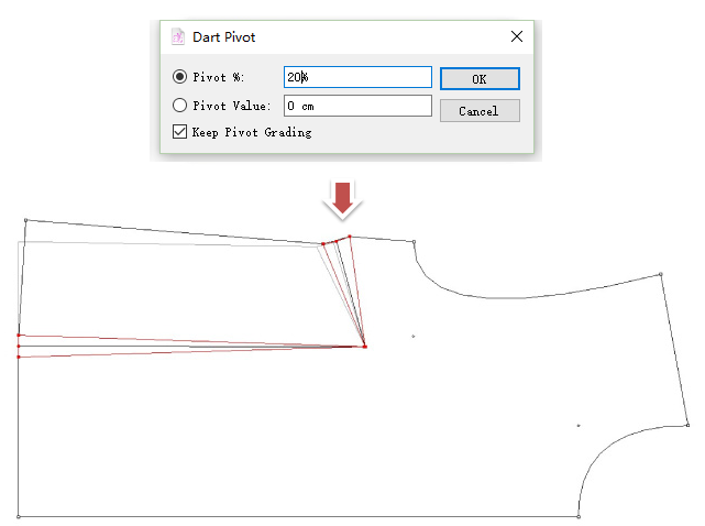
 Dart Transfer
Draw an internal segment;
Select the segment and the dart;
Select
Click the point on which the original dart is closing;
Dialog box appears, enter value and click [OK] button.
Note
The dart will transfer to the side according the clicking point in 4th step.
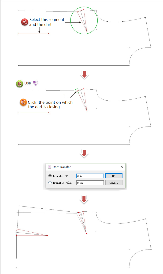
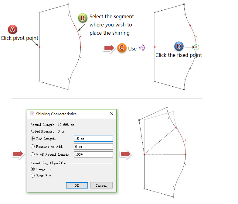
 Shirring
Use this tool creates shirring.
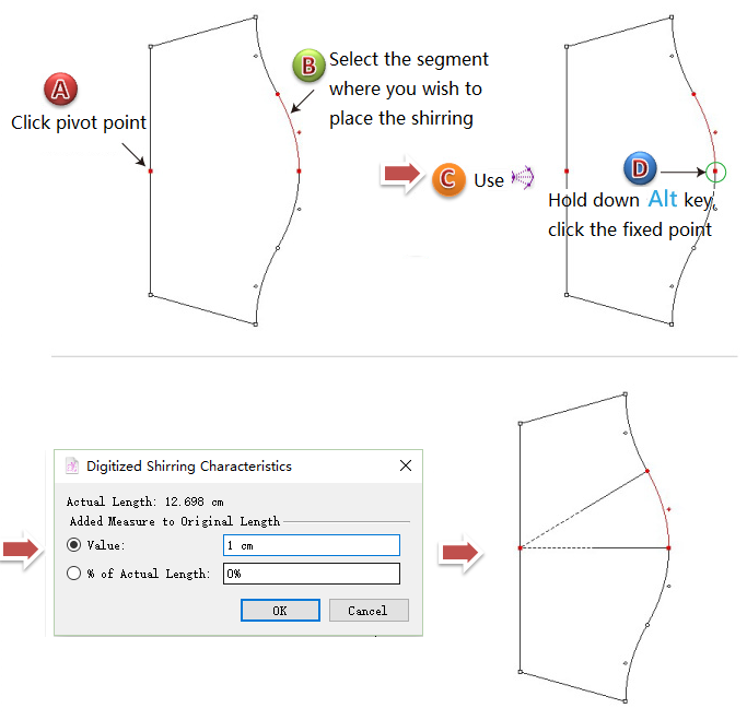
Develop shirring
Select a pivot point and the segment where you wish to place the shirring;
Select
Click the pivot point;
Dialog box opens, enter desired value and click [OK];
Add shirring without spreading the piece
Select a pivot point and the segment where you wish to place the shirring;
Select
Hold down Alt (Windows) or Option (Macintosh) or Alt+Windows (Linux) key, click the pivot point;
Dialog box opens, enter desired value and click [OK];
 Seam Allowance
Allows users to add seam allowances to the contour of a pattern piece. This tool must work on Pieces View, not on Plan View, so users need to set the pieces first.
Note
For more information about how to set piece, please refer to Chapter Two Menu [Treatment] Menu section.
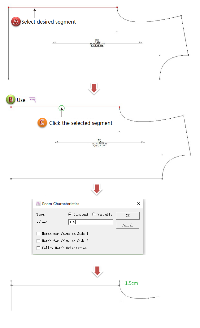
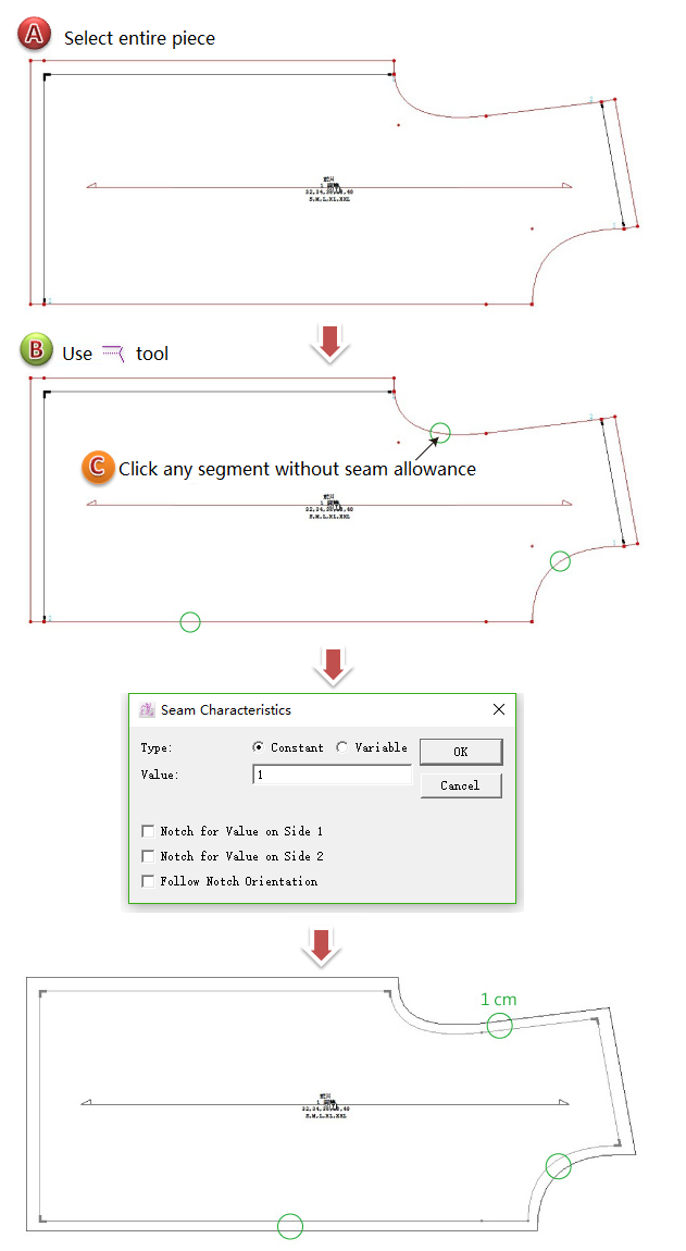
Add seam allowance
Select the desired segment;
Select
Click the selected segment, enter value in the dialog box, click [OK].
If you want to add same seam allowance value to the rest of the segments, repeat the former steps. It won’t influence the previous seam allowance.
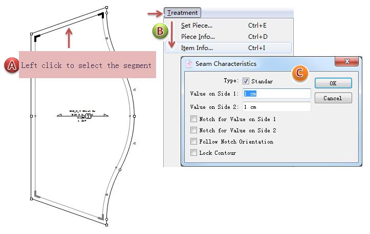
Edit seam allowance
Left click to select the segment which you want to edit the seam allowance;
click [Treatment]-[Item Info] to callout the “Seam Characteristics” box;
Edit the value and click [OK] button to confirm the modification.
How to delete the seam allowance
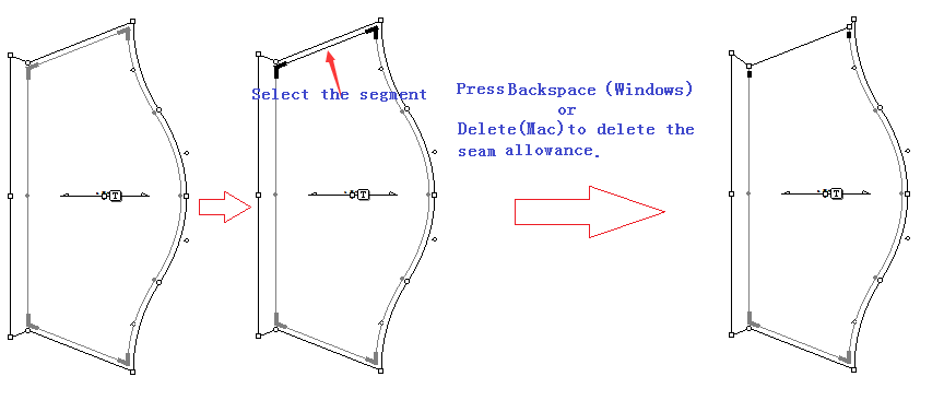
Delete the single segment’s seam allowance
Use pointer tool
Press Backspace(Windows) or Delete(Mac) key to delete the selected segment’s seam allowance.
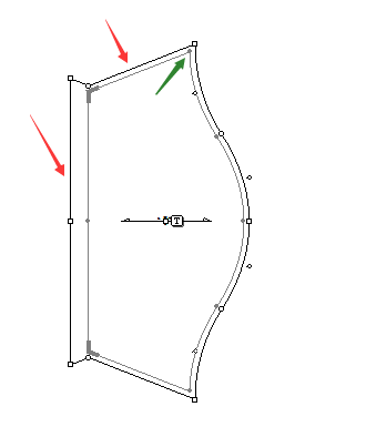
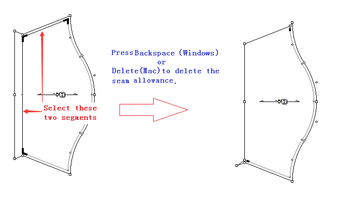
Delete multiple segments’s seam allowance on the same piece
As the below picture shows, now need to delete the two segments’s seam allowance which the red arrows point.
Firstly, you need to add seam corner for the point which the green arrows pointed. The detail steps pls refer to the interduce of the Seam Corner tool.
Hold down the Shift key, use the pointer tool
Press Backspace(Windows) or Delete(Mac) key to delete the selected segment’s seam allowance.
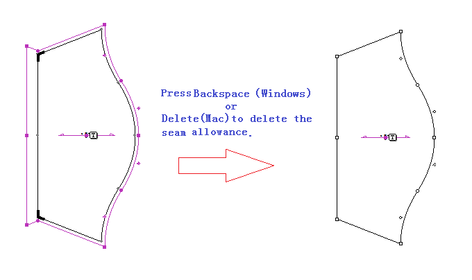
Delete the whole piece’s seam allowance
Use pointer tool
Press Backspace(Windows) or Delete(Mac) key to delete the selected piece’s seam allownace.
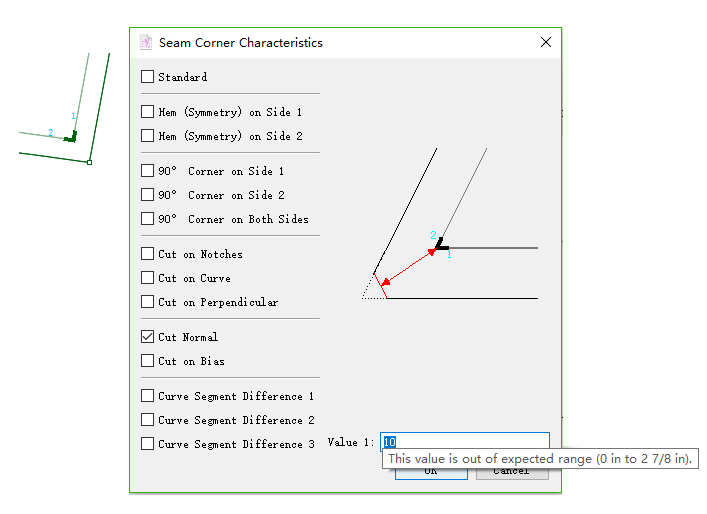
 Seam Corner
Allows users to create a Seam Corner on any sewing line’s mark or regular point. This tool creates a Seam Corner whenever two Seam Allowances meet. Users also can modify the corner if necessary.
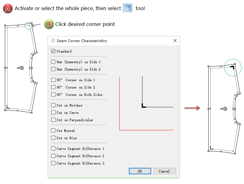
Add a seam corner
Activate the piece with seam allowance;
Select
Click the sewing line point that requires the seam allowance corner;
Dialog box appears, enter value and click [OK] button.
Modify the existing seam corner
Select the corner sign;
Select Menu [Treatment] - [Item Info];
The dialog box opens, modify the information, then click [OK] button.
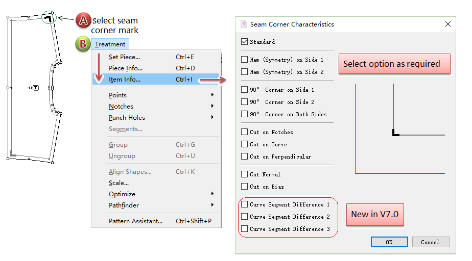
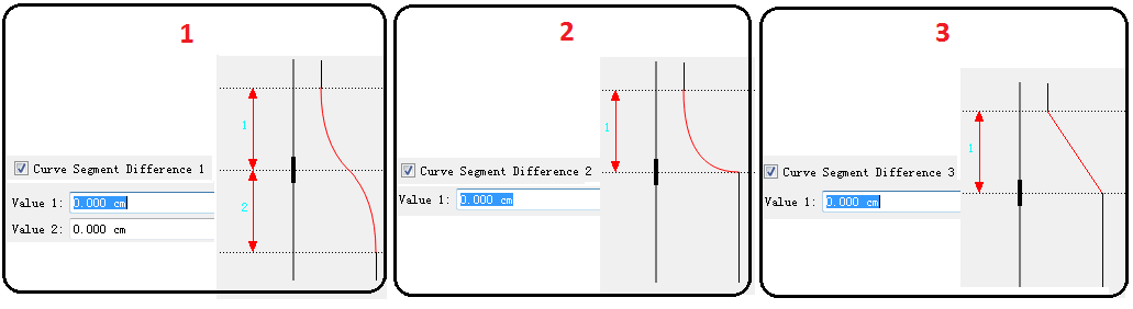
New features in V7.0
Three new options for treatment on seam corner
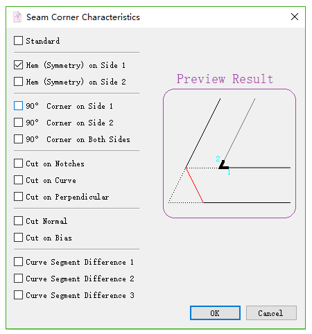
Instant preview for treatment on seam corner
Take Cut Normal as an example:
Show maximum value
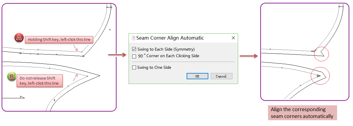
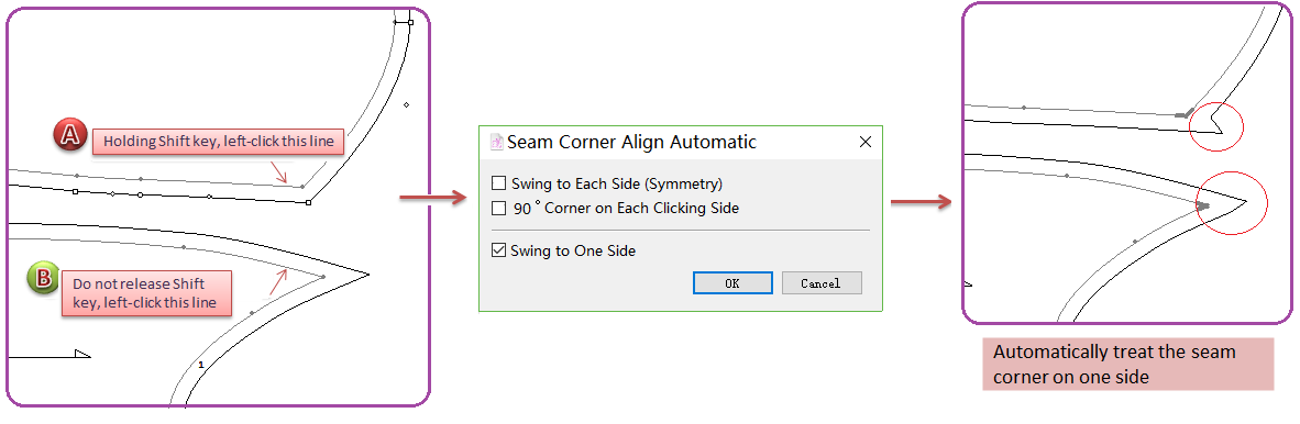
Add Seam Corner Align Automatic
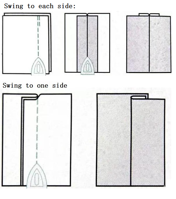
On garment sewing technology, there are technology requirement of swing to each side and swing to one side. So, the seam corner needs to be treated as users’ requirement like swing to each side, swing to one side and aligning seam corner. This new feature is created to help users treat the seam corner more easily and quickly.
Swing to each side
How to do:
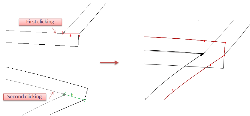
Holding the Shift key, left-click to activate two pieces;
Left-click
Do not release the Shift key, left-click the segment of first desired piece, the cursor becomes a cross, left-click the segment of second piece;
Dialog box appears, select [Swing to One Side] button;
Click OK.
Note
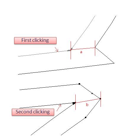
Take the clicking segment as axis and add symmetry seam corner (take the first clicking segment as reference). As the example picture shows, take segment a as reference, the length of segment b is equal to segment a.
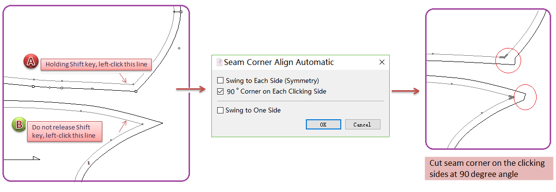
90°corner on each cliking side
How to do:
Holding the Shift key, left-click to activate two pieces;
Left-click
Do not release the Shift key, left-click the segment of first desired piece, the cursor becomes a cross, left-click the segment of second piece;
Dialog box appears, select [90°Corner on Each Cliking Side] button;
Click OK.
Note
Take the clicking segment as axis and add 90 degree seam corner (take the first clicking segment as reference). As the example picture shows, take segment a as reference, the length of segment b is equal to segment a.
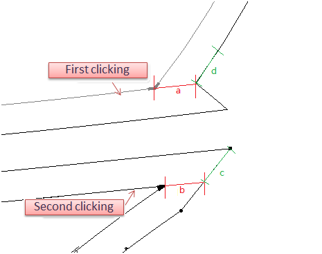
swing to one side
How to do:
Holding the Shift key, left-click to activate two pieces;
Left-click
Do not release the Shift key, left-click the segment of first desired piece, the cursor becomes a cross, left-click the segment of second piece;
Dialog box appears, select [Swing to One Side] button;
Click OK.
Note
Take the first clicking segment as reference. As the example picture shows, the length of segment b is equal to segment a,and segment c is equal to segment d.