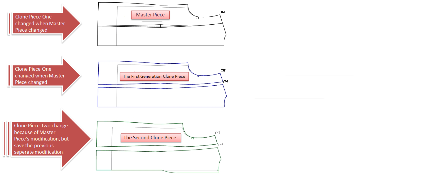
Enhance Clone (Piece Clone)
- Allow users to set piece clone on Planning Piece.
- Allow users to create more than one clone.
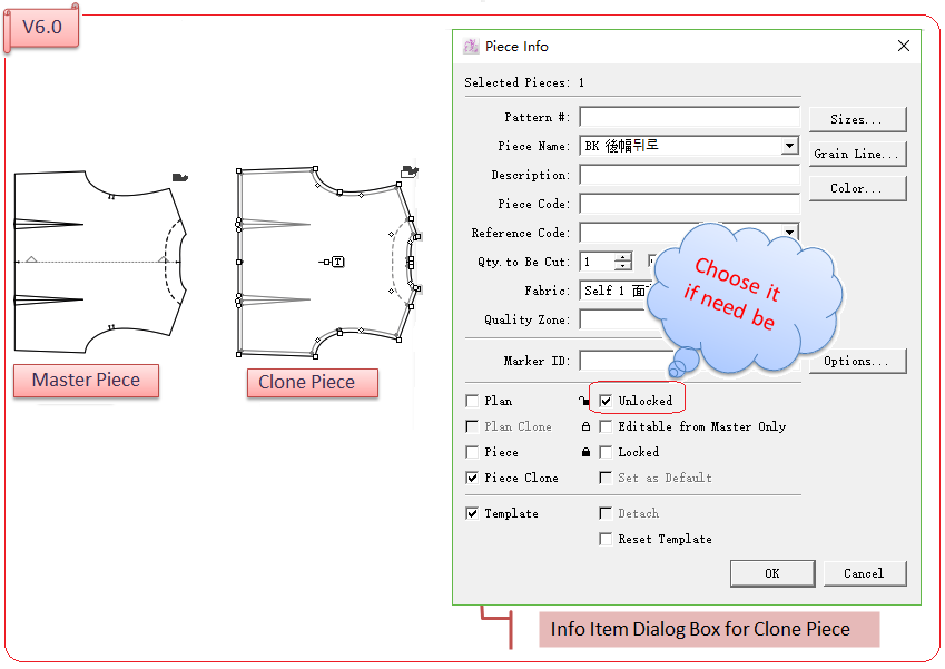
- Allow users to modify the clone piece without changing the master one. However, when the master piece or the former one of clone pieces is modified, the clone pieces will also be modified according to changed piece, and save the previous individual modification.
Set piece clone on planning piece(s)
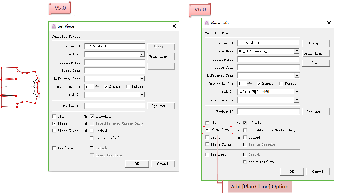
Add [Plan Clone] option, enable users to set clone on plan piece.
Create more than one Clone
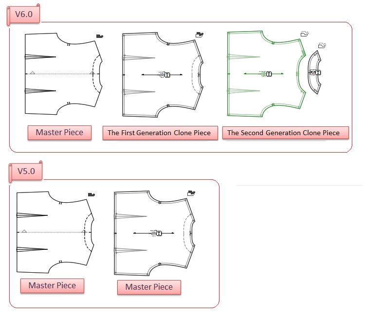
In V6.0, allow users to create more than one Clone generations: Master piece - the first generation Clone piece - the second generation Clone piece
But in V5.0, only allow to set one Clone generation: Master piece - Clone Piece One
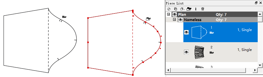
The clothes-like icon on the upper-right corner of the piece represents the relation of Clone generations. Different meanings of different icons are shown as follow:
:Master Piece
:the first generation Clone piece (cloned from Master Piece, and changed by the modification of Master, or modified individually)
:the second generation Clone piece (created from the first generation Clone piece, and changed by the modification of master/the first generation Clone piece, also allow to be modified individually)
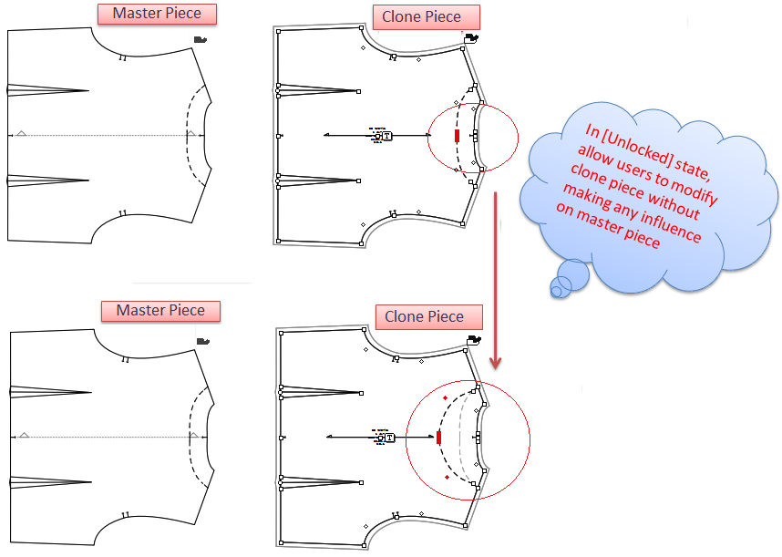
Modify Clone Piece Individually
In [Unlocked] state, allow users to modify the clone piece individually without changing Master piece in V6.0.
備註
It’s not allow to modify clone piece individually because there’s no unlocked state for Clone Piece in V5.0. The [Unlocked] option show gray representing not allow to choose.

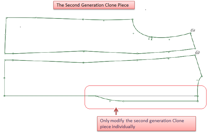
After modifying clone piece seperately, it will be modified when master piece or the previous clone piece is changed, and also save the previous individual modification.
For example, modify the second generation Clone piece shown in following picture:
When Master Piece or previous Clone Piece is modified, the second generation Clone piece also gets changed, and save the previous individual modificaiton:
備註
The Modification here includes modification of piece contour/internal segment , grading modification , seam allowance modification .
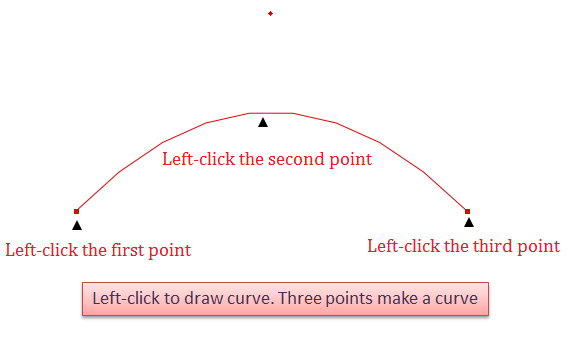
Enhance Curve Tool
Allow users to create curve by using this tool. Users can draw the curve directly, and do not have to use Segment Tool to draw a segment and then drag it into curve by using Curve Tool; allow users to move a group of control/regular points by entering desired value or by freehand, which improves the efficency of pattern-making.
Draw a curve as desired
Select
Curve Tool, left-click to draw a curve. Three points make a curve.
備註
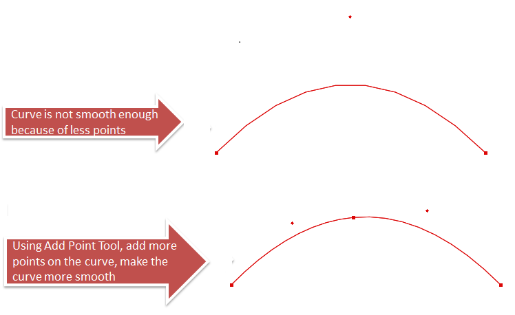
Three points make a curve. Because the limition of points, the curve is not smooth enough, so users can add more points on the curve by using Add Point Tool to adjust the curve.
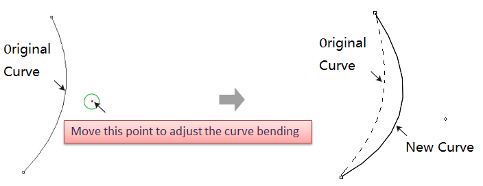
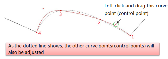
Allow users to move the curve point to modify the bending of the curve.
Move a group of curve point (control point) as desired
Select the desired curve;
Select
Left-click one of the curve point without releasing the mouse button, drag the curve to desired area then release the button.
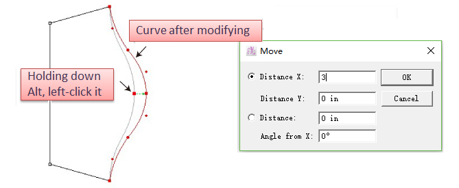
Move a group of curve points (control points) or regular point by entering specific value
Select the desired curve;
Select
Holding down Alt key (Windows) or Option key (Mac), left-click the desired point or segment;
Dialog box appears, enter specific number and click OK.
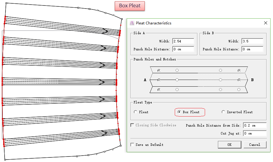
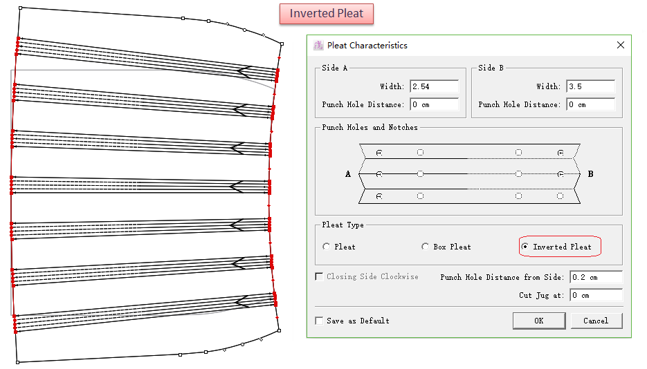
Enhance Pleat Tool  
Allow users to devolop more pleats more quickly and easily, avoid repeating the operation.
Add pleat type [Box Pleat] and [Inverted Pleat], users select it as desired.
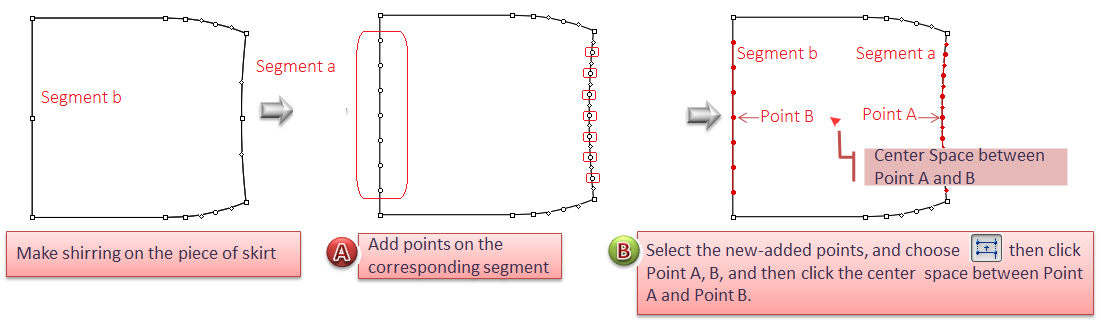
Develop multiple pleats
Add points to the corresponding segments, like Segment a and Segment b; (If develop 7 pleats, you need to add 7 points to each segment)
Select the new-added points, choose
Left-click one of the points in Segment a (e.g. Point A), then click corresponding point (Point B) on Segment B;
備註
The points you clicked are fixed points, the pleats will be developed to two sides.
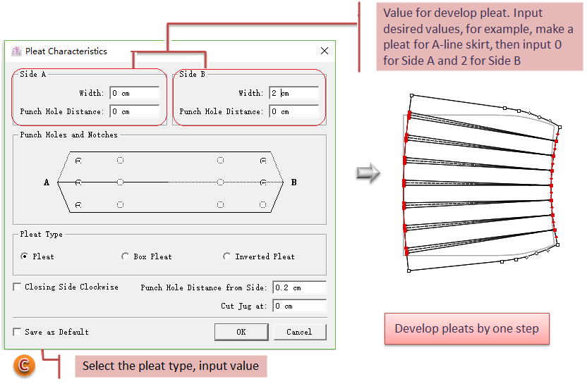
Dialog box appears, choose desired pleat type, and input desired values, click [OK], it will develop mutiple pleats at a time.
備註
[Width of Side A] allows 0 as a value, but [Width of Side B] doesn’t. So to develop mutiple pleats with one side’s width value 0, notice the order of clicking: the part click firstly is Pleat A, and then the Pleat B.
Add two pleat types: [Box Pleat] and [Inverted Pleat]
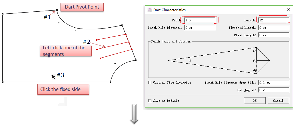
Enhance Dart Tool  
Allow Users to create multiple darts at a time, accelerate the efficiency of pattern-making and avoid repeating operation;
Allow users to locate the dart in the center;
Add two dart characteristics: [Internal Width] and [External Width].
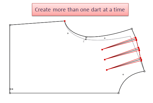
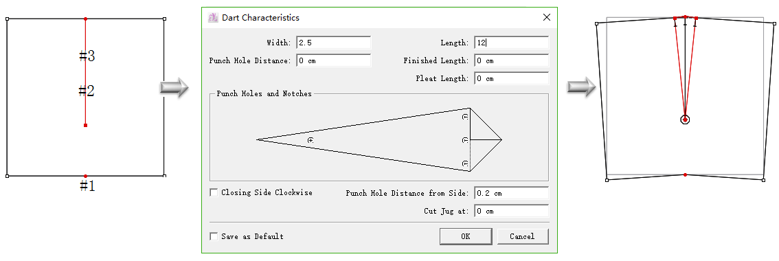
Create multiple darts at a time
Add segment(s) that darts will locate in the desired position (the new segments must attach to the piece contour), then select the segments;
Select
Click dart pivot point (shown as following picture #1);
Click one of the segments (shown as following piecture #2, to confirm the dart’s position);
Click the fixed part (shown as following picture #3);
Input values in the dialog box, click [OK].
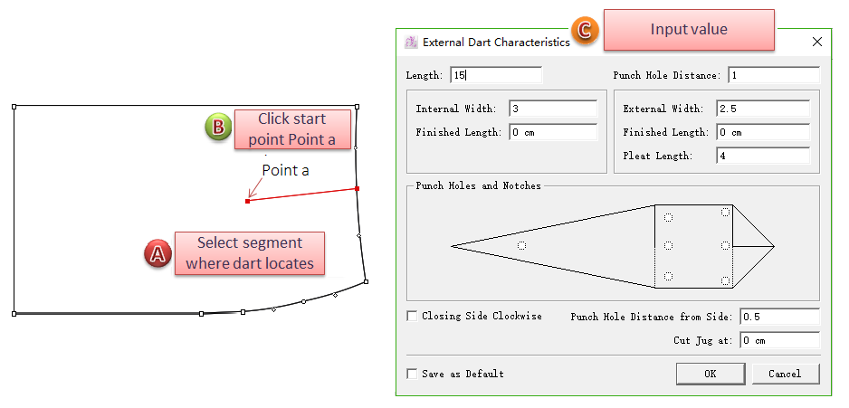
Locate dart in the center
Draw a segment where the dart will be developed (the segment need to attach to the piece contour), and then select the segment;
Select
Click the dart pivot point (shown as picture #1);
Click the segment defining the dart position (shown as picture #2);
Enter values in the dialog box, click [OK], finish developing a dart.
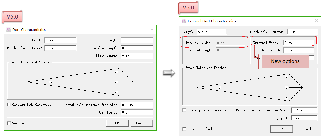
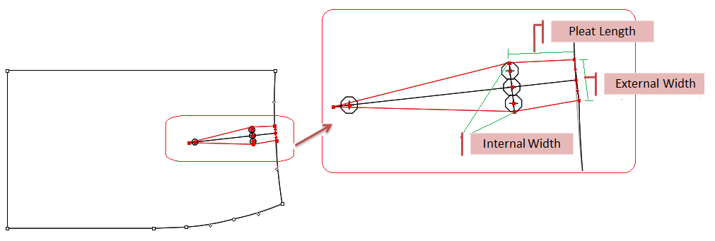
Add two dart characteristics: [Internal Width] & [External Width]
備註
Only enter value into [Pleat Length] can the [Internal Width] be lit up and available to enter values.
Select desired internal segment;
Select
Click the start point of selected internal segment, like Point a in the picture;
Enter values in the dialog box, click [OK].
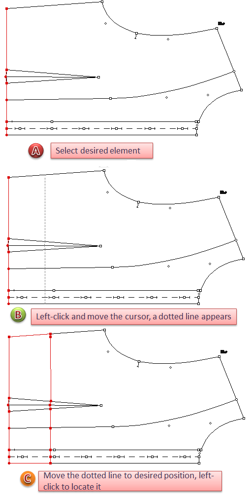
Enhance Parallel Tool
Allow users to draw parallel line by dragging the cursor, accelerate the efficiency of pattern-making.
Draw parallel line as desired
- Activate the piece, select the desired element;
- Select
tool;
- Left-click the desired element, move the cursor, a dotted line appears;
- Move the dotted line to desired position, left-click to locate it.
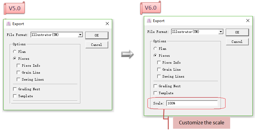
Enhance Export Illustrator Format Function
Add [Scale]. Allow users to customize the scale. Scale range: 10% ≤ Scale ≤ 100%.
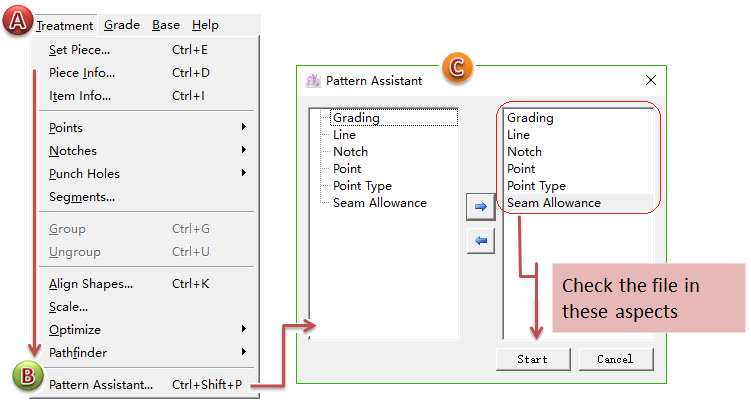
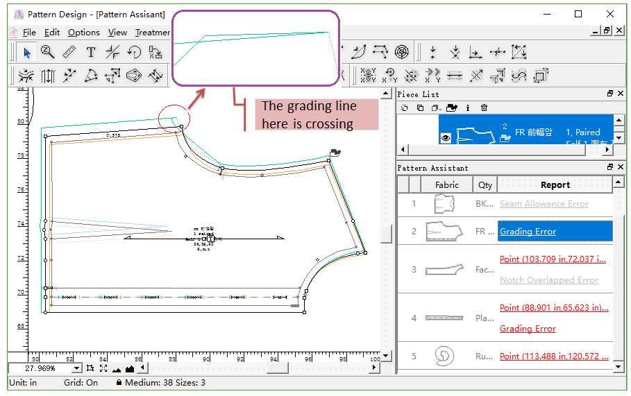
Add Pattern Assistant
The system will check over the piece file and find out the errors automatically. It shows the error information in detail so that reduces the errors while making pattern pieces.
Finishing drawing the pattern piece(s), users can start [Pattern Assistant] to check if there’s any error in the file before it is sent out to product.
Click Menu [Treatment] then [Pattern Assistant];
[Pattern Assistant] dialog box appears, the system will check over the file in Grading, Segment, Notch, Point, Point Characteristics, Seam Allowance to find out the errors, click [Start] to begin checking.
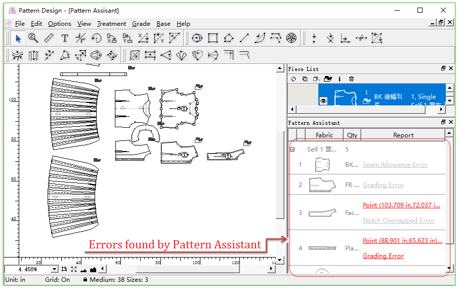
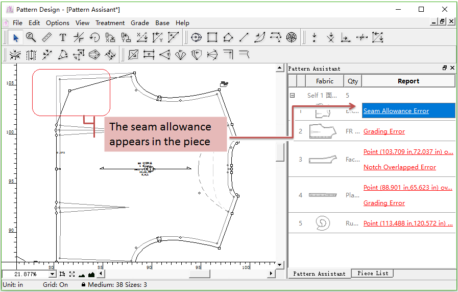
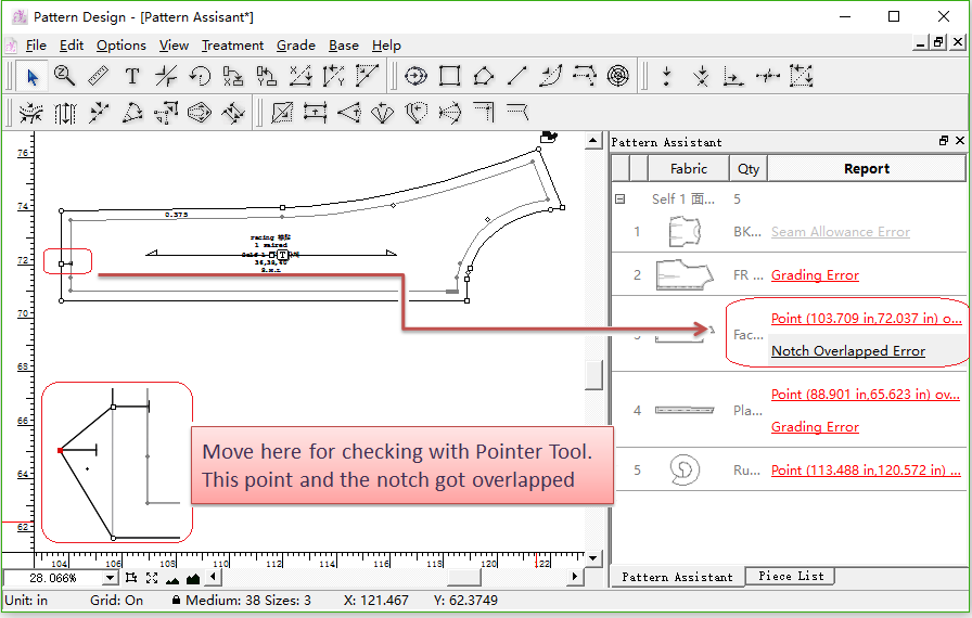
If the system find out any error, it will show them in the floating window in the sidebar of software window.
Click one of the error items in the floating window, the piece with problem will be magnified and viewed in the middle of work area.
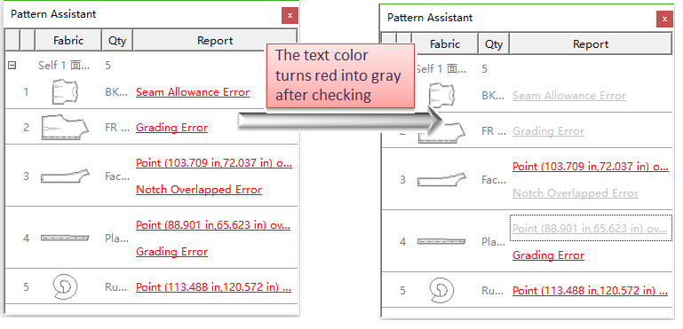
備註
If the error information was checked already, the color would turn red into gray.
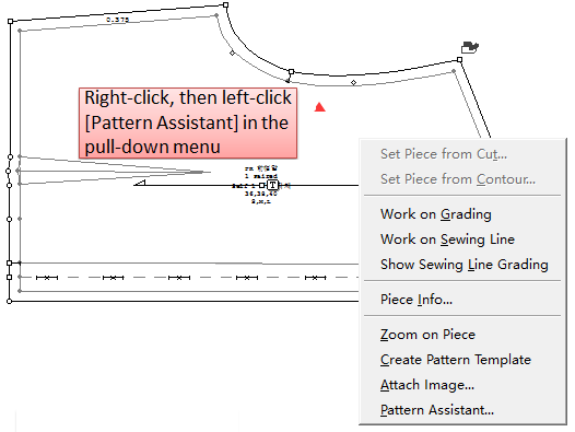
Check specific piece with [Pattern Assistant] by manual
Right-click the piece need to be checked and click [Pattern Assistant] on the pull-down menu, then repeat the step 2,3 and 4 shown as above to find out the error information.
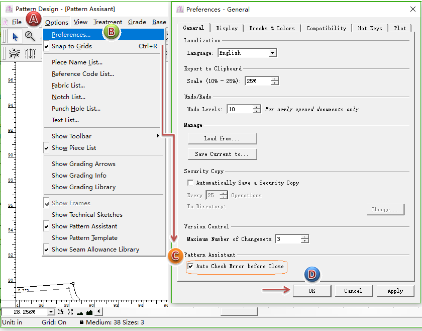
Auto check error before close
Set [Auto Check Error before Close], the software will automatically execute [Pattern Assistant] to check over the file before it is closed.
Picture shows how to set:
備註
You can press Esc key to force to quit this function.
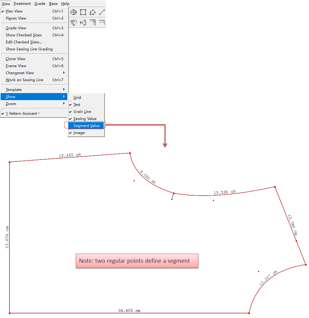
Add [Show Segment Value] on the segment
Allow show the segment length value on each segment, let the users check the segment length more easily and quickly, increase the efficiency of pattern-making.
Show all the segment values
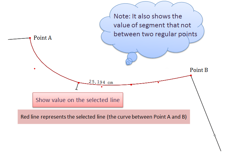
Show selected segment value
How to do:
- Select the desired segment;
- Select
Ruler Tool (or press shortcut key R );
- Press R key again, the value is shown on the selected segment.
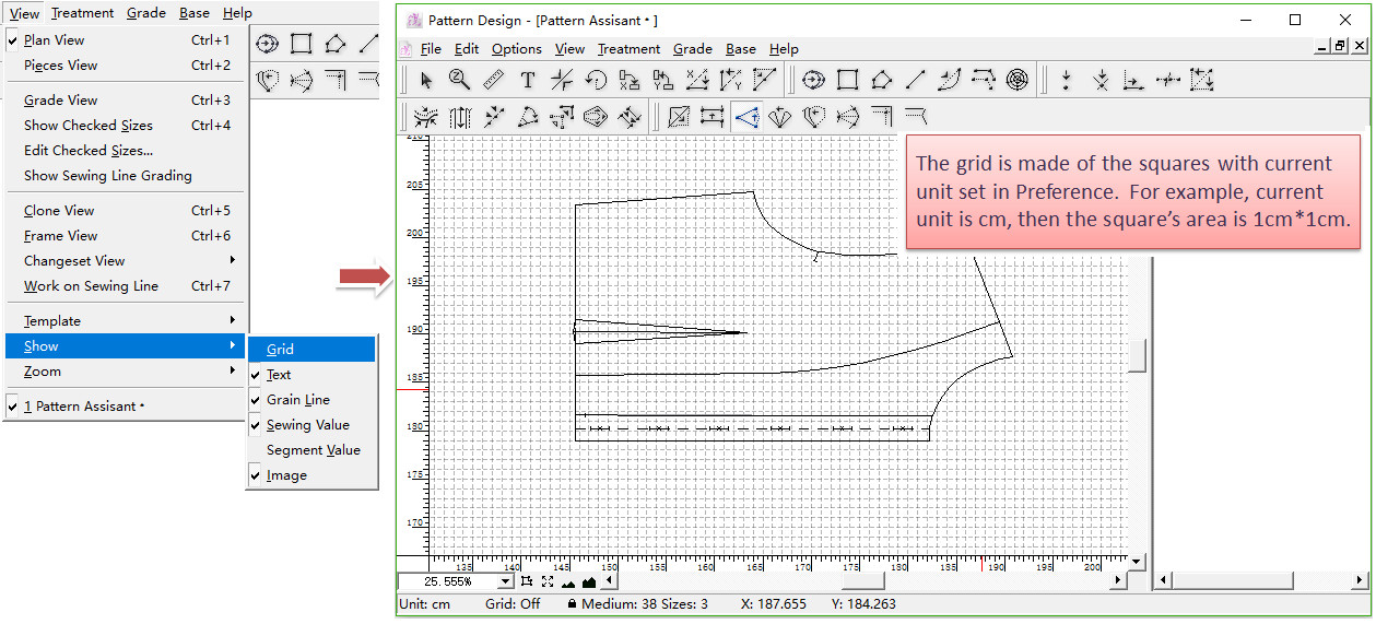
Add [Show Grid]
Show grid background on the working area. Users can choose it as desired. It helps increase the efficiency and accuracy of pattern-making.
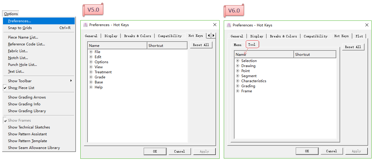
Add Hotkeys Pre-setting for Tools
Allow users to pre set the hotkeys for tools, which caters for the users.
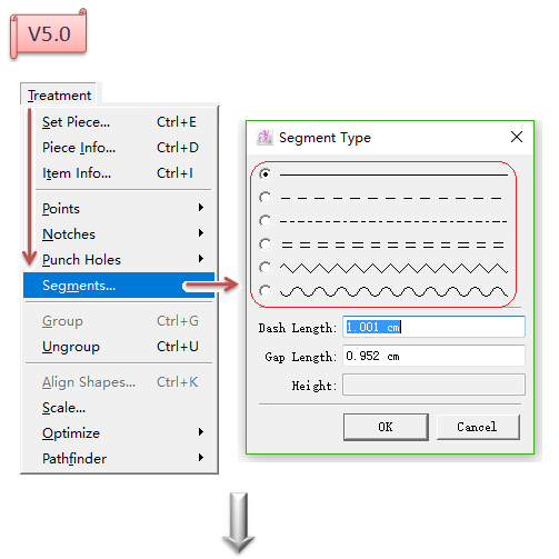
Add Segment Types (Cutting Segment Types)
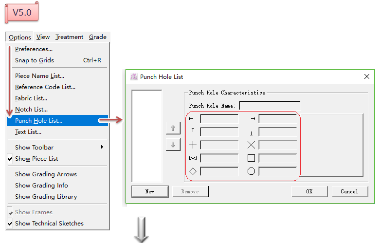
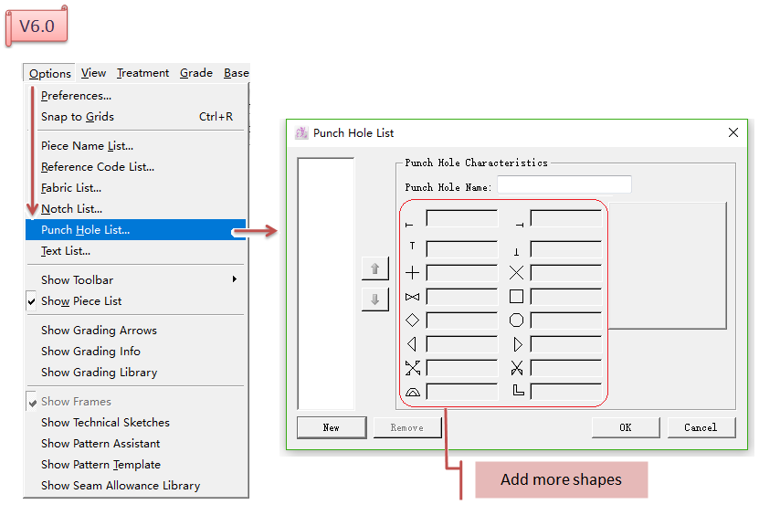
Add More Shapes in [Punch Hole List...]
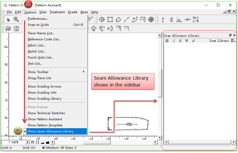
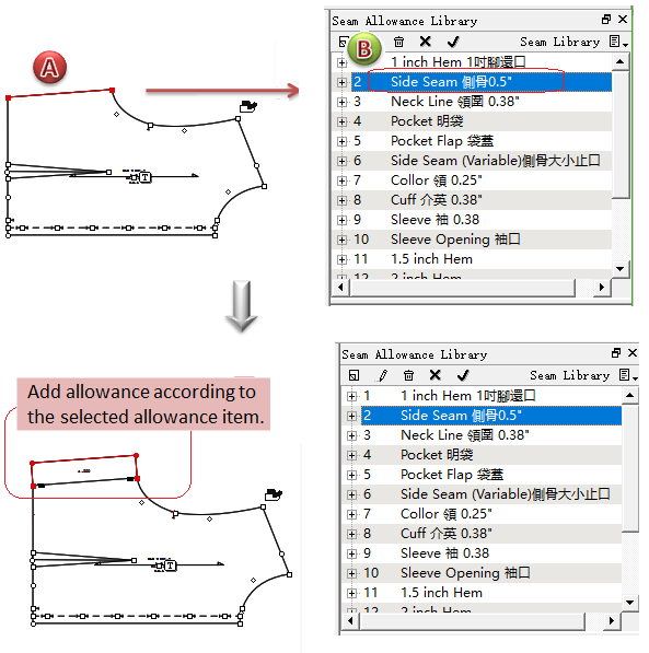
Add Seam Allowance Library
Seam Allowance Library allow users to establish the seam allowance database to save the pre-set allowance values.
Before using Seam Allowance Library, users should open its window shown in the sidebar.
How to do:
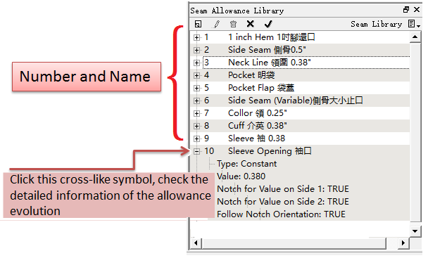
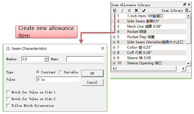
Users can creat more allowance values in the library as needed. Each library can include at most 999 allowance evolutions. Through the window of Seam Allowance Library, users can check each seam allowance’s number and name. Left-click the little cross-like symbol in front of the number and it shows the detailed information of the seam allowance evolution, like type, value and so on.
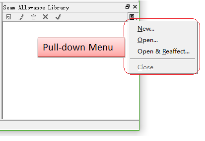
Introduction of the pull-down menu of Seam Allowance Library
New... : Create a new seam allowance library;
Open... : Open the existing seam allowance library made and saved before;
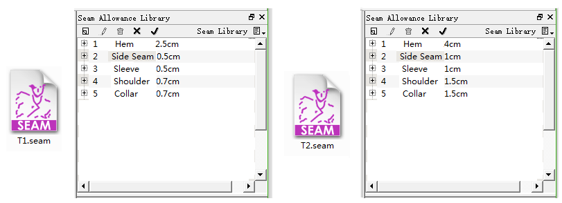
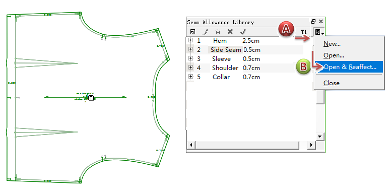
Open&Reaffect... : Open other seam allowance library, and replace allowance evolution of current pieces with the new allowance library;
備註
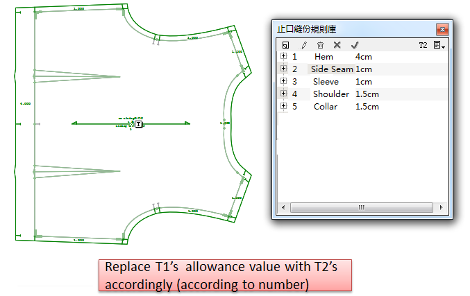
It replaces the seam allowance library according to the number. For example, the seam allowance library T1 applied in the current file has seam allowance with number 1,3,4,8. Now click [Open & Reaffect...] to open seam allowance library T2, then T2’s seam allowance with number 1, 3, 4, 8 will be replaced by T1’s and applied in the current file directly.
Close: Close the current seam allowance library.
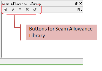
Introduction of the buttons of Seam Allowance Library
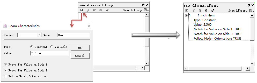
New : Add new seam allowance item in the library;
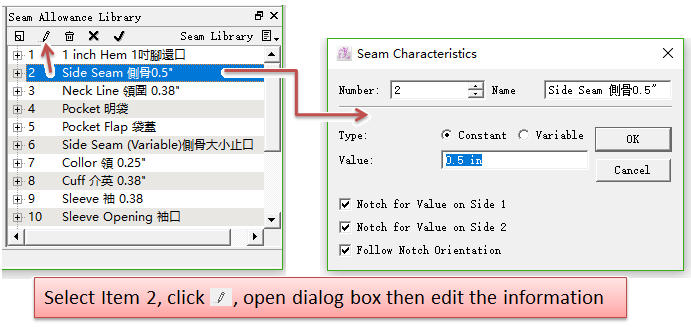
Edit : Edit an allowance item;
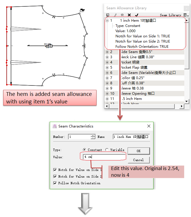
Choose desired item, click this button, (or double-click the desired item),open the [Seam Characteristics] Dialog box, edit desired item.
Delete : Remove the selected item;
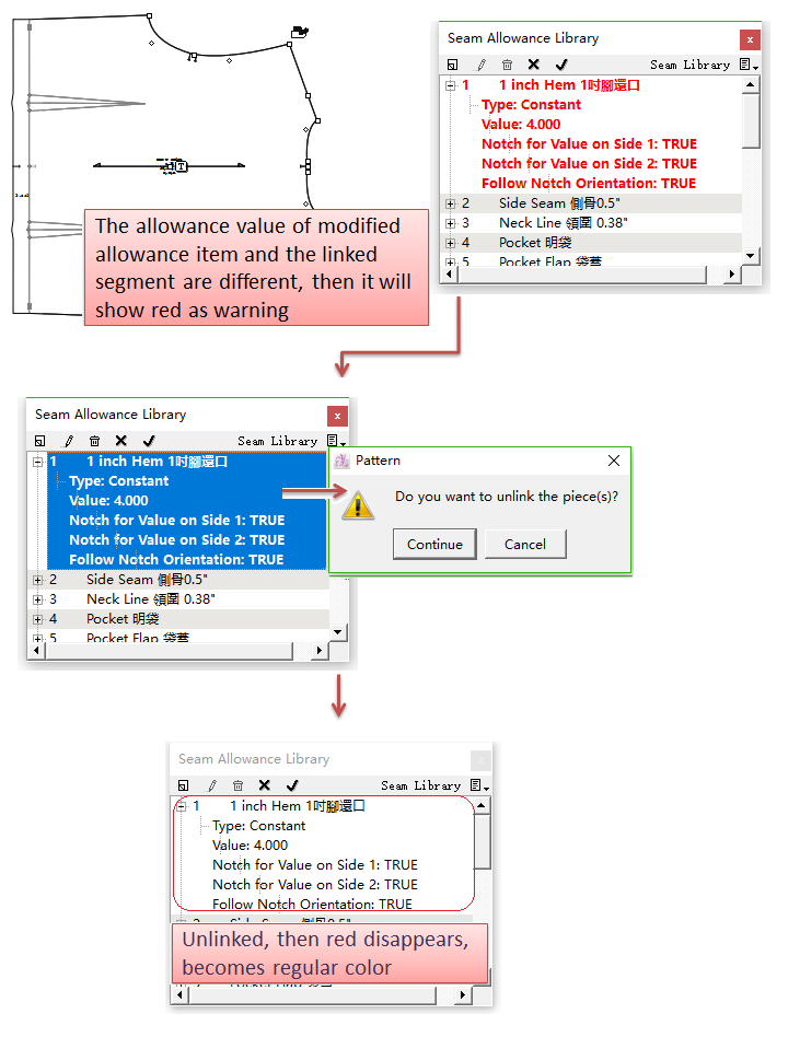
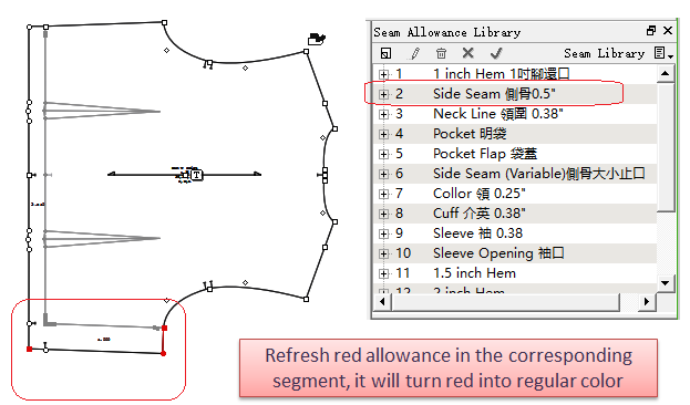
Cancle: Cancle the connection between red allowance item and the segment.
備註
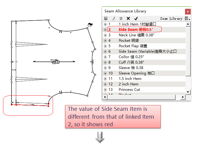
What is Red Allowance Item: some allowance of a segment in a certain piece is added by applying the Seam Allowance Library. If the seam allowance item or the allowance of the segment has been modified, this seam allowance item and the segment’s allowance will be different, then it will be shown in red as a warning in the window.
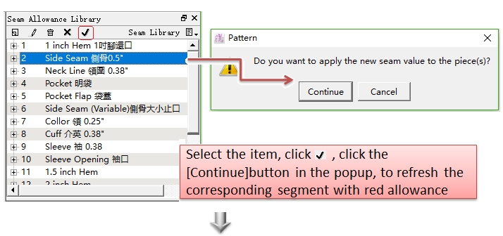
Apply : refresh allowance of segment
In Seam Allowance Library, if the allowance item is in red, then select it, and left-click
How to Create Seam Allowance Library
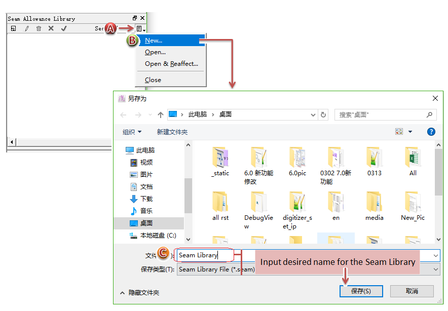
Open the pull-down menu in the Seam Allowance Library window and click New...;
Dialog box appears, enter name, click Save;
Left-click
備註
It will save the seam allowance item automatically, no need to save manually.
How to open Seam Allowance Library File (.seam) and apply it
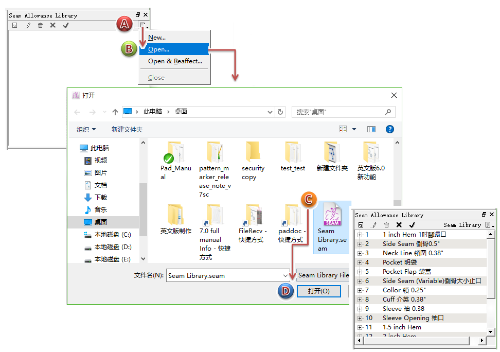
Open the file (.seam)
Click Open... in the pull-down menu of Seam Allowance Library;
Choose the specific path in the [Open] Dialog Box, select the desired seam allowance library and click [Open].
Apply Seam Allowance Library
Choose the segment needs to add allowance;
Left-click seam allownce item, now the allowance has been added into the segment already.
Open new library to replace current one, and apply it in the current file
For example, here are two seam allowance libraries T1 and T2. A pattern file apply T1 to add allowance. Now a user wants to use T2 to apply in the current pattern file.
How to do:
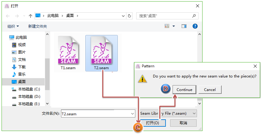
Click Open&Reaffect... in the pull-down menu of Seam Allowance Library;
Select T2.seam allowance file from correct path, and click [Open];
Dialog box appears to ask, then click [Continue].
Add Pattern Template
Allow users to save the frequently-used pattern pieces to a database for applying them more quickly and easily. This database is the equivalent of Base.
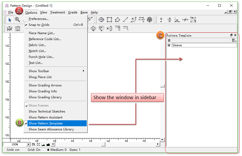
Before using [Pattern Template], open the [Pattern Template] window, showing it in the sidebar.
How to do:
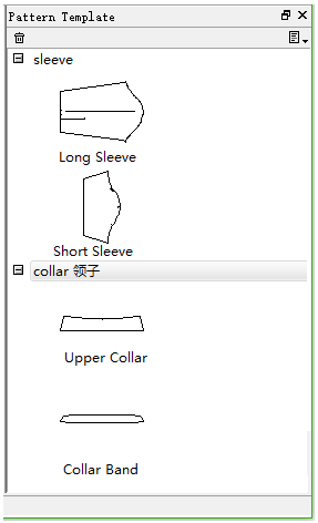
Users can create more than one frequently-used pattern pieces in [Pattern Template].
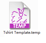
The file format saved is (.temp).
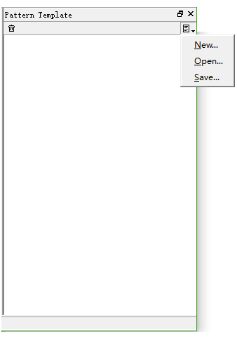
Introduction of buttons and full-down menu of Pattern Template
Delete : Remove all the selected piece shown in the window of Pattern Template;
New... : Create new item of pattern piece;
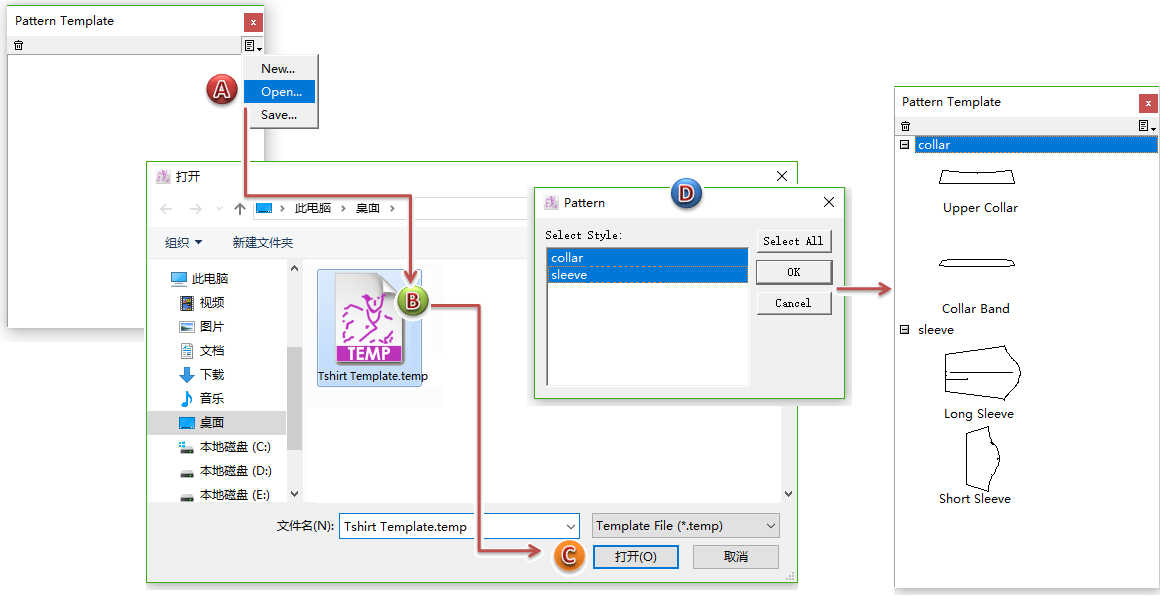
Open... : Open the pattern template file that is ready-made and saved (or sent from other users);
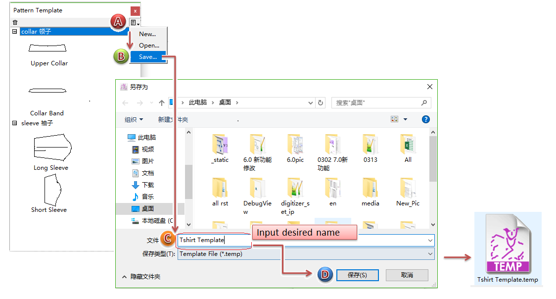
Save : Save a new-built/modified pattern template, for sharing the file to other users.
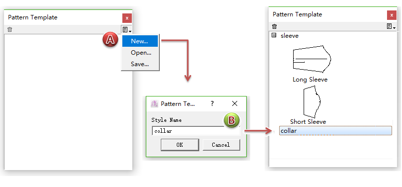
How to create pattern template
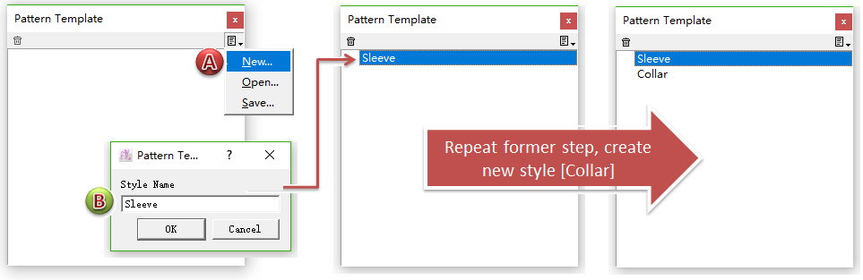
Left-click [New...] in the pull-down of Pattern Template, the dialog box appears and enter the name, for example, my desired pattern template includes two items Sleeve and Collar;
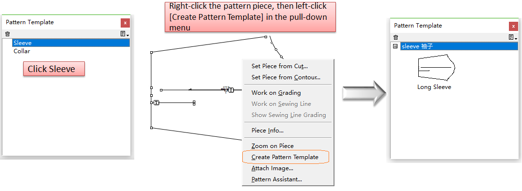
Select [Sleeve] Item in Pattern Template window, then move the cursor to the desired piece and right-click it, pull-down menu appears, click [Create Pattern Template];
備註
repeat the steps shown above to create more frequently-used template piece in different items.
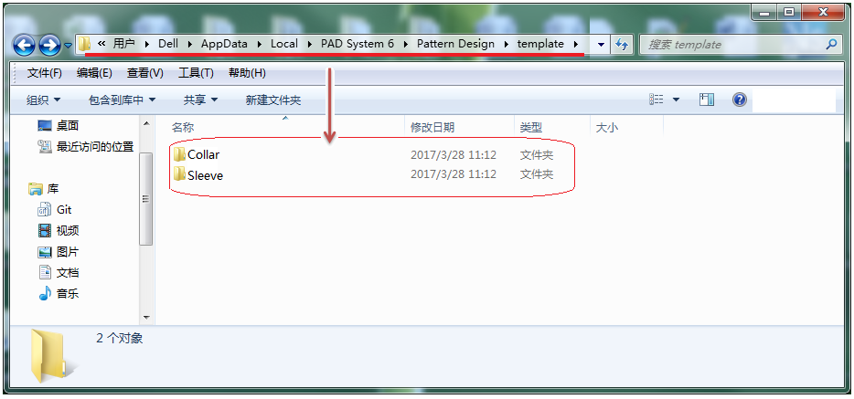
It will save the pattern template automatically to the path:
If you want to share the pattern template to other users, click [Save...] in the pull-down menu. The template file format is (.temp), send it to other users.
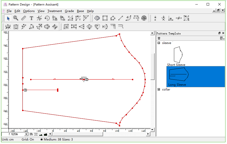
How to use the piece from pattern template
Open the Pattern Template Window in the sidebar. If the pattern templates are created locally, the software will read and show them in the window, then go to Step 3 directly.
If the pattern template file (.temp) is from other computer or user, then open it manually:
Left-click the desired piece in Pattern Template, and do not release the mouse button, drag it to the working area then release the button:
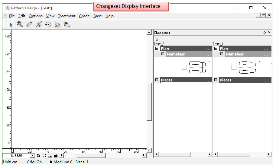
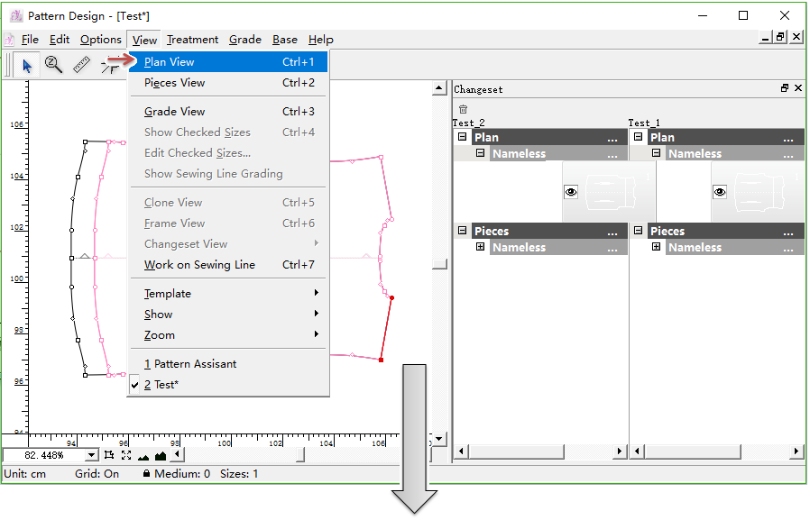
Add Changeset Function
This function is added for users to manage and check the modification of the files.
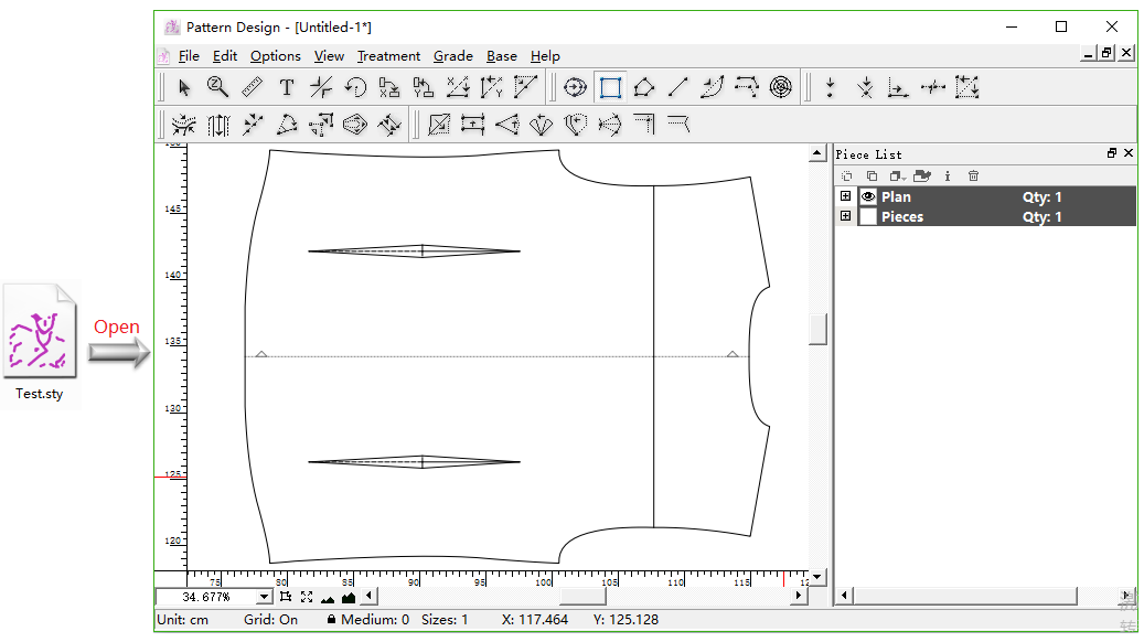
This function just save at most 3 changeset, for example, the current file is Test.sty, the changeset that can be saved are Test_1,Test_2 and Test_3 during the process of modificaiton.
How to use [Save Changeset] function
Take a pattern file Test. sty as an example:
Open Test.sty;
Modify the file, like lengthen the clothes, then left-click menu [File] - [Save Changeset]. Then click menu [View] - [Changeset View], it saved a changeset Test_1.
備註
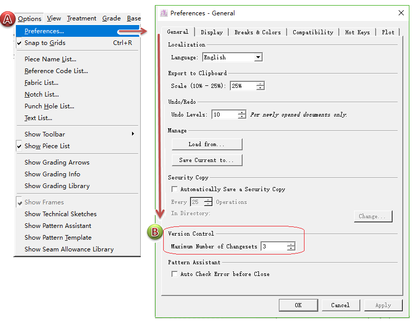
After each modificaiton, repeat to click [Save Changeset], it will save at most 3 changeset. Users can set it here:
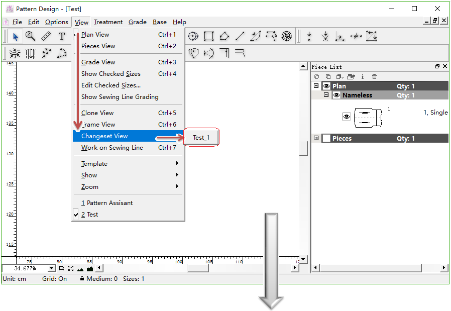
Click menu [View] - [Changeset View] - Test_1, it turns to the changeset display interface. Test_2 is the lastest modified file, Test_1 is the former one.
備註
The newest file after modificaiton is always the last one, if save two changeset Test_1 and Test_2, then the newest current file is Test_3 after modificaiton.
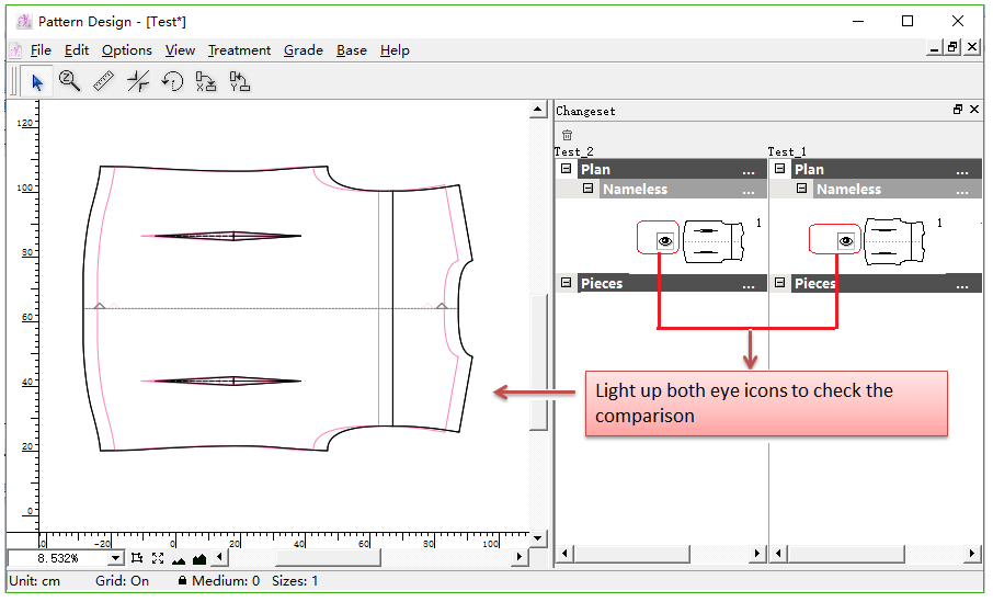
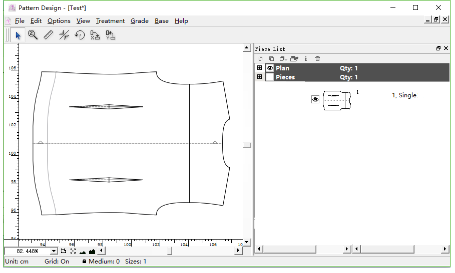
Light up the eye icons before the piece item in the sidebar, the piece shows in the working area and align to the center point by defualt. Test_2 (the newest file after modificaiton) shows in black, Test_1 (the changeset before modification) shows in red.
備註
These tools now are available under the Changeset View state. They can be used to move/measure/rotate...
Use
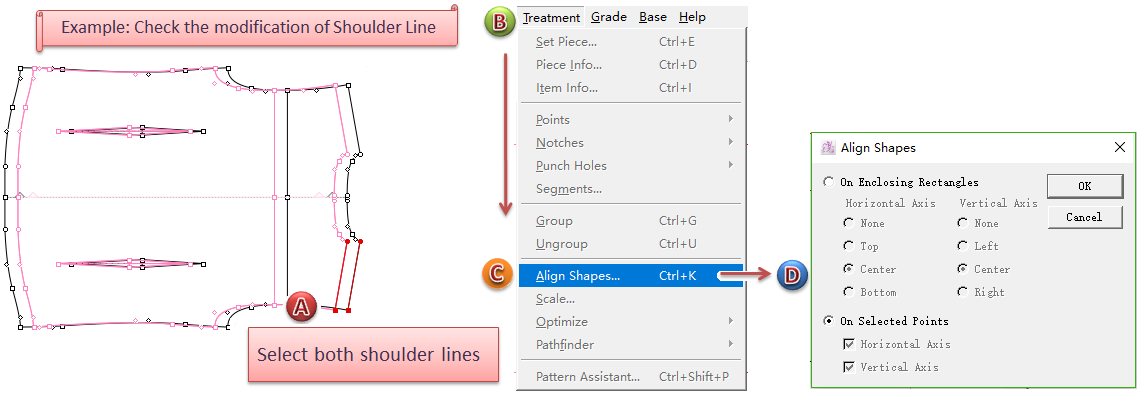
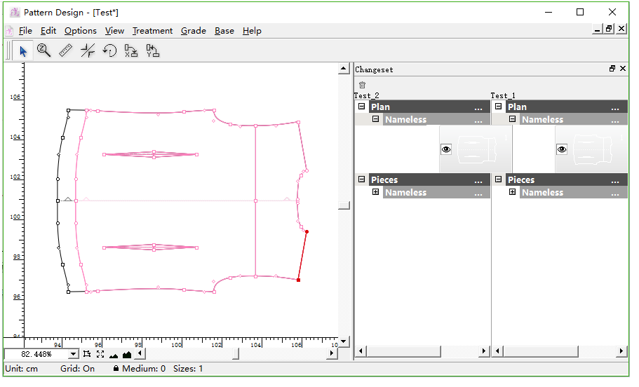
Pointer tool to move and align the pieces to check modificaiton, or click menu [Treatment] - [Align Shapes] to align pieces and check the modificaiton.
For example, select [Align Shapes...] to check:
備註
Click menu [View] - [Plan View] or [Pieces View], it will turn changeset display interface into regular display interface for drawing pieces.
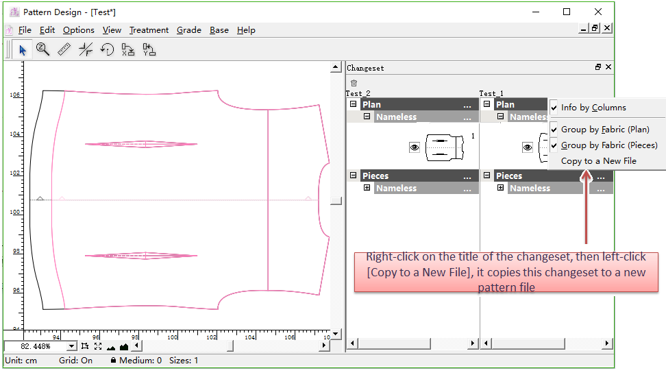
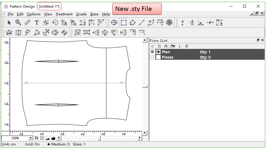
Copy changeset to a new .sty file
Move the cursor to corresponding changeset title and right-click it, the pull-down menu appears, click [Copy to a New File], the interface will go to a new one of a new (.sty) file, all the selected pieces of changeset will paste in the new (.sty) file.
Add Segment Sync  
Simulate to close the dart(s) / shirring, or merge the pieces together, and to adjust the contour as desired by using this tool.
備註
Before using this tool, recommend the users to enable the Shadow function, so that uesrs can check and compare the results.
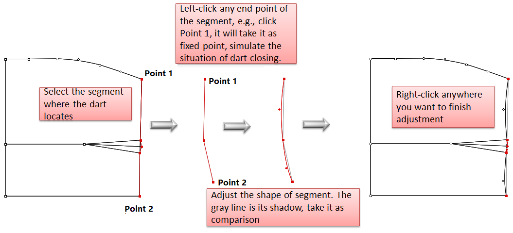
Simulate dart closing, modify the segment
Select desired element (the segment where the dart locates);
Select
Left-click any endpoint of the segment (the one you click is the fixed point);
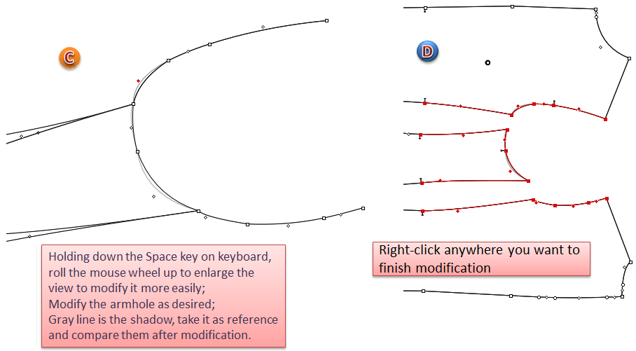
Now it shows the state of dart closing, you can modify the segment by dragging it; (if the piece is too small to modify, press the Space key on your keyboard and roll the mouse wheel to enlarge the view)
備註
Modify it in two ways:
- Left-click the desired point and drag it to the position you wish, release the button; or left-click the segment without releasing the button, drag it to a curve directly.
- Select the desired point, modify it by using the arrow keys on your keyboard.
Modify the segment. Right-click to finish modification.
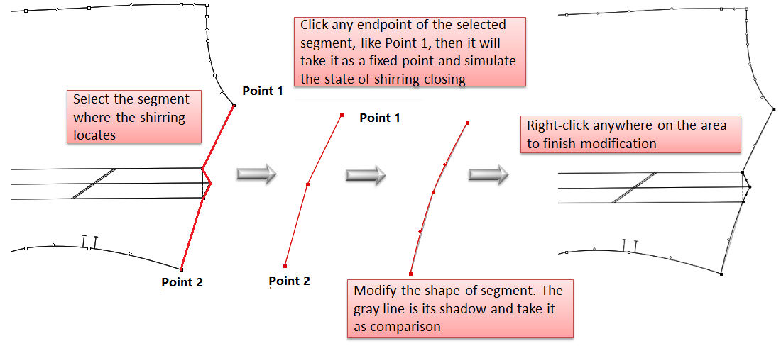
Simulate shirring closing, modify the segment
Select desired element (the segment where the shirring locates);
Select
Left-click any endpoint of the segment (the one you click is the fixed point);
Now it shows the state of shirring closing, you can modify the segment by dragging it; (if the piece is too small to modify, press the Space key on your keyboard and roll the mouse wheel to enlarge the view)
備註
Modify it in two ways:
- Left-click the desired point and drag it to the position you wish, release the button; or left-click the segment without releasing the button, drag it to a curve directly.
- Select the desired point, modify it by using the arrow keys on your keyboard.
Modify the segment. Right-click to finish modification.
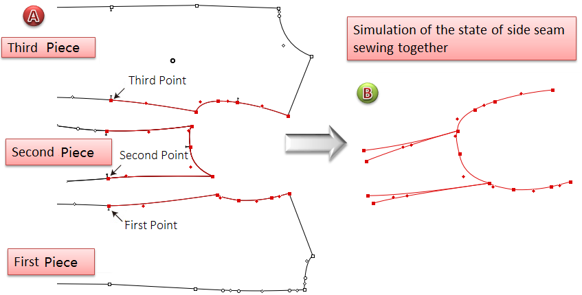
Simulate pieces sewing, modify the segment
For example, simulate to sew the pieces together, modify the shape of armhole.
Select the desired segment;
Select
Left-click the first point (the point on the first section), the second point (the one on the second section), and the third point one by one;
Now it shows the state of side seams sewing together, you can modify the shape of armhole by dragging it (if the piece is too small to modify, press the Space key on your keyboard and roll the mouse wheel to enlarge the view);
備註
Modify it in two ways:
- Left-click the desired point and drag it to the position you wish, release the button; or left-click the segment without releasing the button, drag it to a curve directly.
- Select the desired point, modify it by using the arrow keys on your keyboard.
Modify the shape of armhole. Right-click to finish modification.
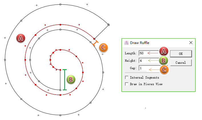
Add Ruffle Tool  
Enable users to make the pattern pieces of ruffle hem or A-line skirt, increase the efficiency and save time.
Draw piece of ruffle hem
Select
Left-click on the desired location;
Dialog box appears, enter values into it, click [OK].
Draw piece of A-line skirt
Repeat the steps as above.
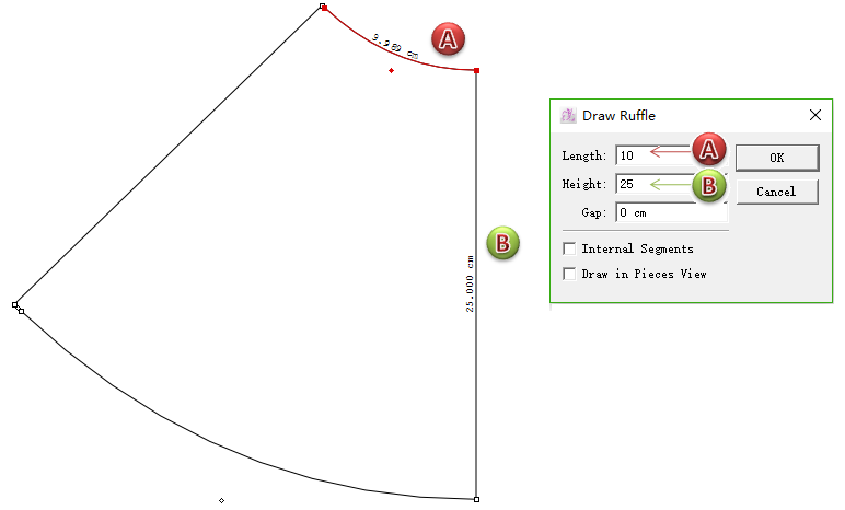
備註
Internal Segment : draw it as internal contour of the piece, each segment can be removed individually.
Draw in Piece View : draw it as a pattern piece directly.
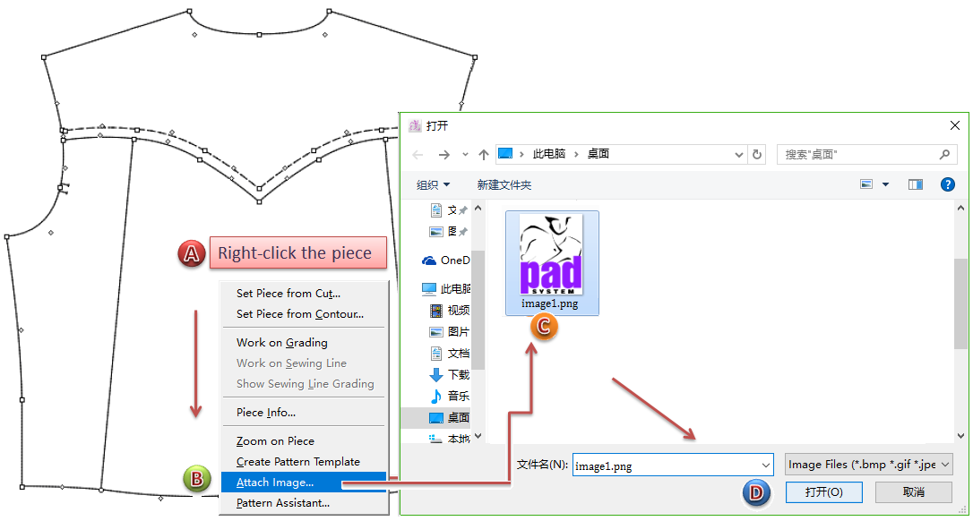
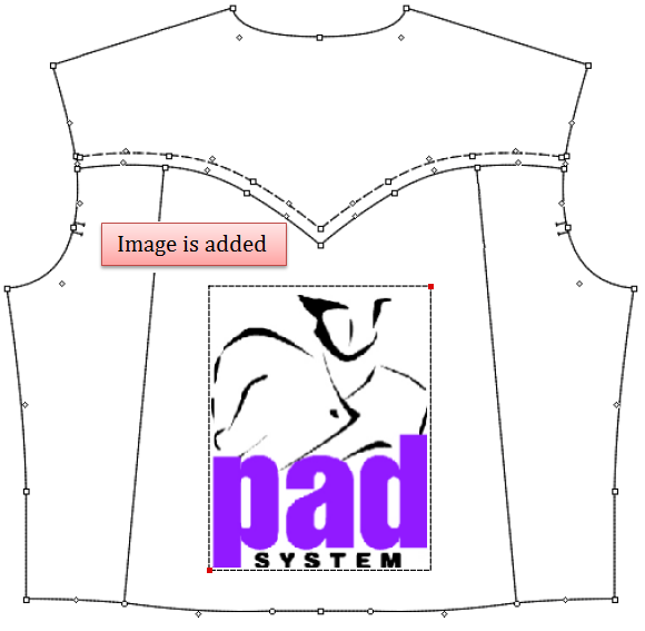
Add [Attatch Image...]
Allow users to add image on the piece directly, enable users to add the printing, embroidery and other images on the piece directly.
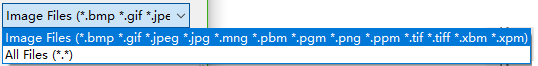
Available image format:
How to add image on the piece
Right-click on the desired position, pull-down menu appears, click [Attach Image...];
Dialog box appears, go to the desired path to select the image file, then click [OK].
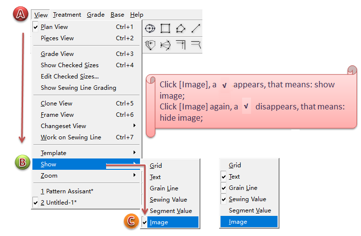
How to show/hide image
Click menu [View] - [Show] -[Image] to show or hide image on the working area:
Select [Image] to show image;
Unselect it to hide image.
How to move the image
If the image doesn’t locate on your desired position, you can:
- Select [Pointer] tool, choose the image, hold down the left mouse button to drag the image to your desired position.
- Select [Pointer] tool, choose the image, press arrow keys on your keyboard to move the image to your desired position.
備註
How to rotate the image
Rotate the image by freehand, or rotate it at N° round angle(N° is mutiples of 15°), or rotate it at precise angle value.
Rotate image by freehand
- Select desired image;
- Select
tool;
- Click the fixed pivot point, then click anywhere you want, drag the pointer to rotate;
- Release the mouse button.
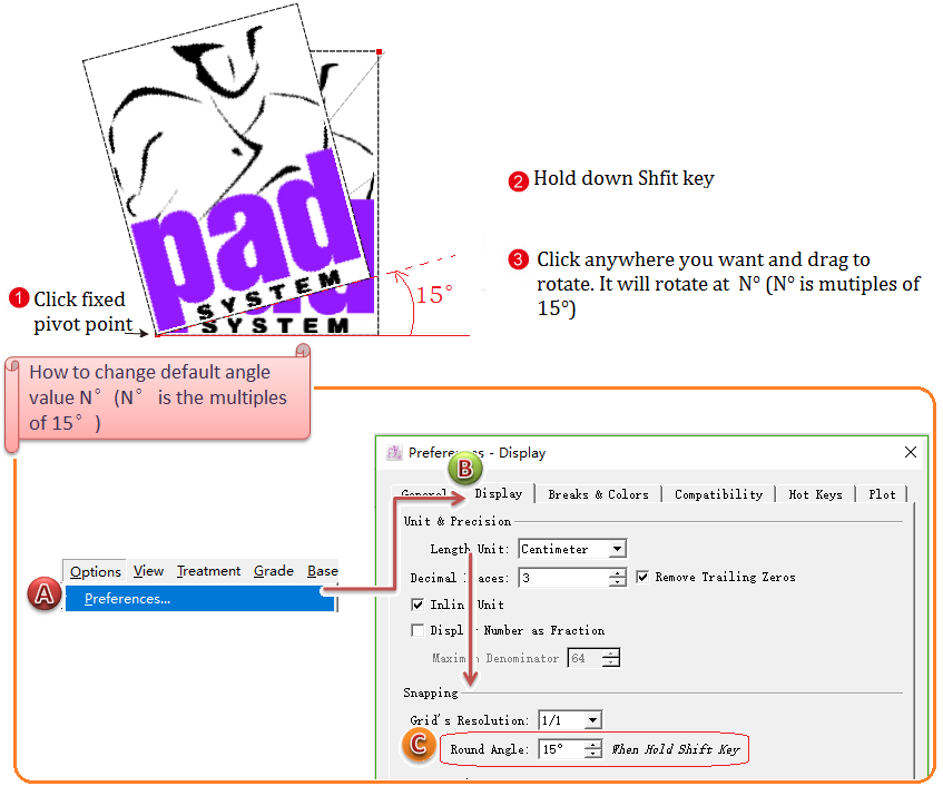
Rotate image at N° round angle
Select desired image;
Select
Click fixed pivot point, press Shift key without releasing it, then click anywhere you want and drag to rotate. It will rotate at N° (N° is mutiples of 15°).
Release Shift key and mouse button.
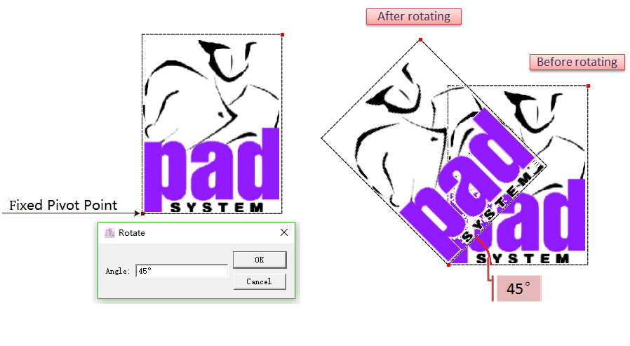
Rotate image at precise angle
- Select desired image;
- Click
- Holding down Alt key (Windows) or Option key (Macintosh), click the fixed pivot point;
- Dialog box appears, enter desired value, click [OK].
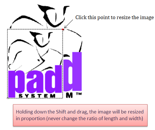
How to resize the image
- Select
tool;
- Select the desired image;
- Left-click the point at the upper left corner, drag it to resize the image.
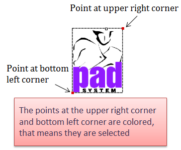
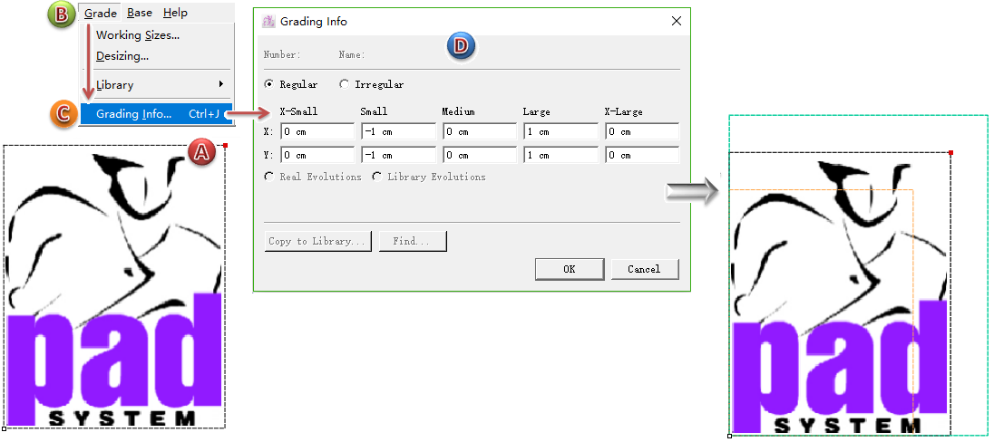
How to manipulate grading on the image
Allow manipulate grading on the regular points at the buttom-left corner and upper-right corner.
How to do:
Select the desired point (for example, the regular point at the upper-right corner);
Click menu [Grade] - [Grading Info...] to open grading info dialog box;
Enter values, click [OK].
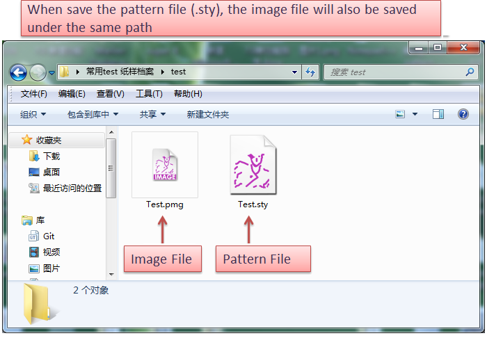
Save image file
When you save the pattern file (.sty), the image will also be save under the same path (pattern file and image file are saved in the same directory). Image format is .pmg, shown as following picture:
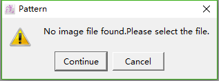
Lost image file
If:
- change the name of pattern file (.sty);
- change the name of image file (.pmg);
- the pattern file (.sty) and image file (.pmg) are in different path (Error moving file or lost sending file);
then it will lost the image file (that’s to say, fail to read corresponding image file while open the pattern file), dialog box appears:
Continue - select image file manually;
Cancle - close dialog box, and replace the image with a rectangle shape.
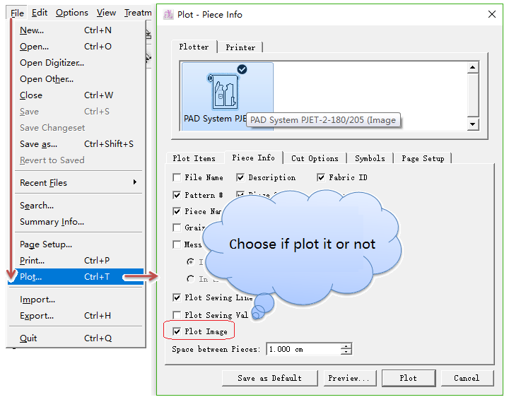
Print image
Print the image while print the pattern file.
備註
Now PAD OEM Plotter & HP (Hewlett Packard) Printer can print the pattern piece and its images. Other printer or plotter can print its frame only.
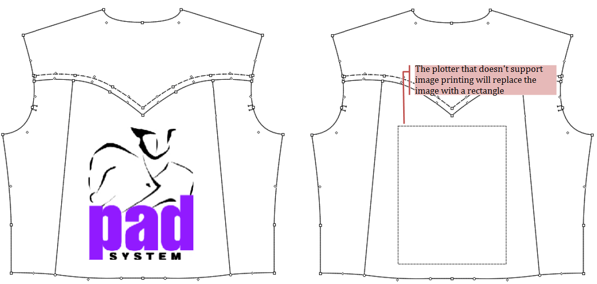
Export the pattern file with images as other formats
Export the pattern file with images as other formats, like DXF-AAMA, DXF-ASTM, Illustrator (.txt), Plotting File (.plt). Then the image will be shown as a rectangle:
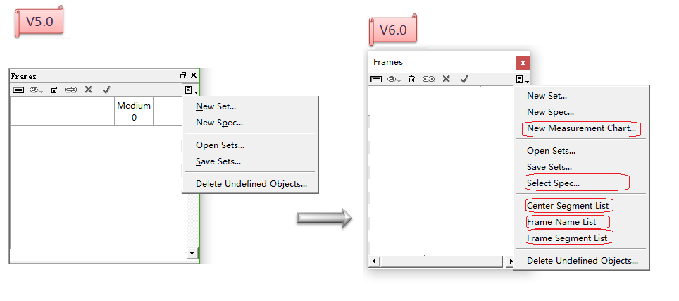
Optimize Frame Segment
- Allow users to preset the frequently-used name list.
- Simlify the operation of setting Frame.
- Add function of creating internal Frame.
- Add [New Measurement Chart...] item.
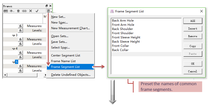
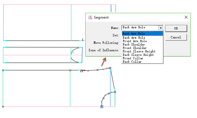
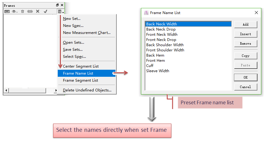
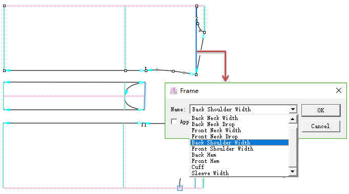
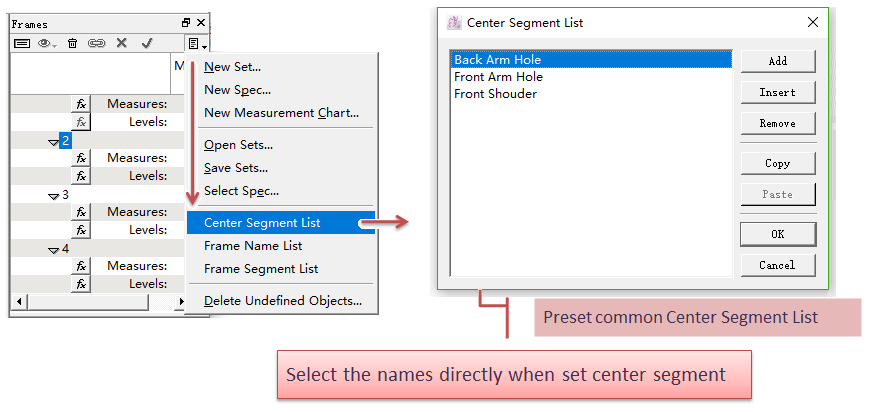
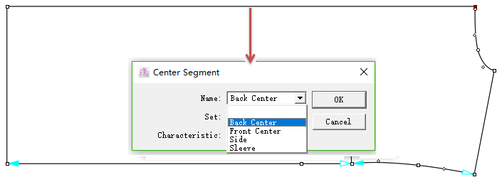
Preset the frequently-used name list
Frame Segment List
Set the common frame segment names previously, so users can use it directly when set the segments.
Frame Name List
Set the common Frame names previously, so users can use it directly when set Farme.
Center Segment List
Set the common center segment names previously, so users can use it directly when set the main item (center segment).
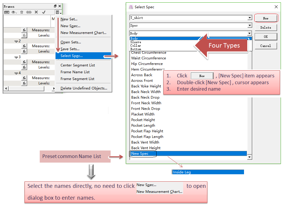
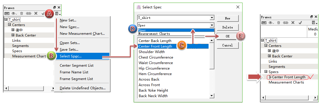
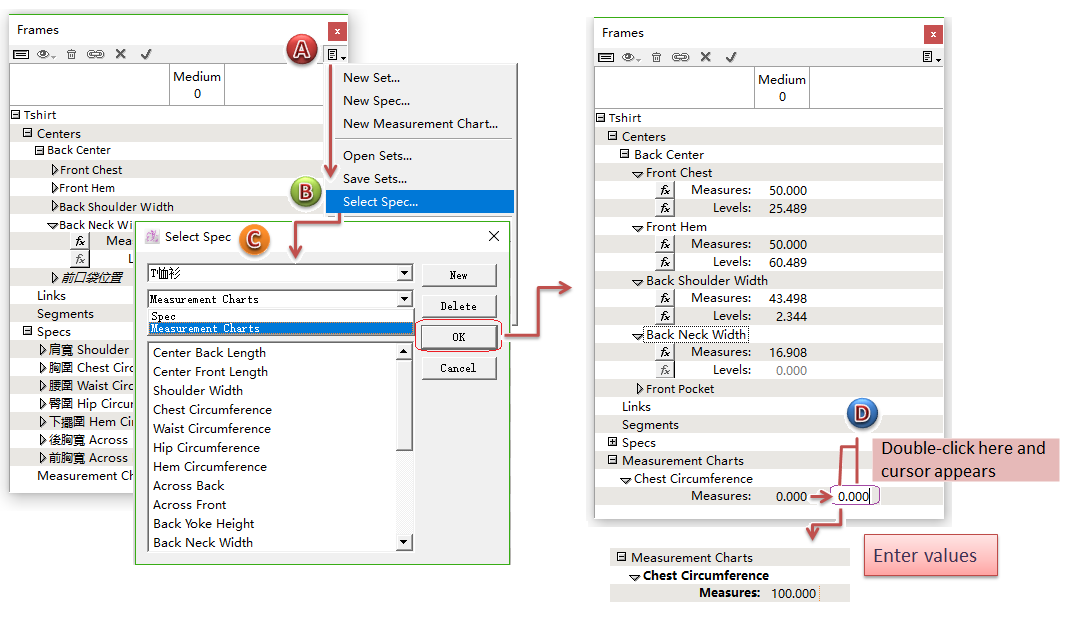
Select Spec...
Set the names of common styles like bodice, sleeve, collar and bottom(includes pants, skirt, trousers...) previously. These names can be used in:
[Spec...] list;
[Measurement Chart].
How to use the preset names:
- Open [Select Spec...] Dialog box;
- Select desired name;
- Select the desired item, [Spec] or [Measurement Charts];
- Click [OK] button, the selected name will be settled in the corresponding item.
For example, use the preset name settled under the item [Spec]:
Simplify the operation of setting Frame
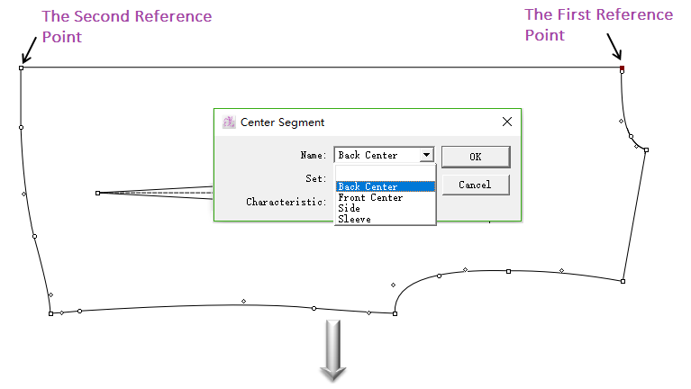
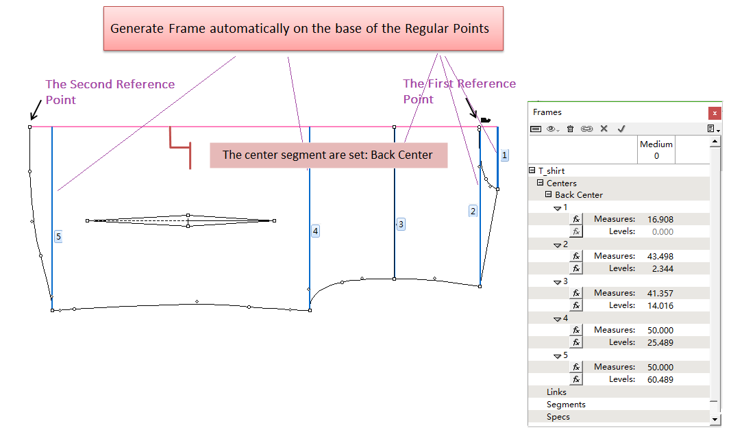
Generate Frame automatically
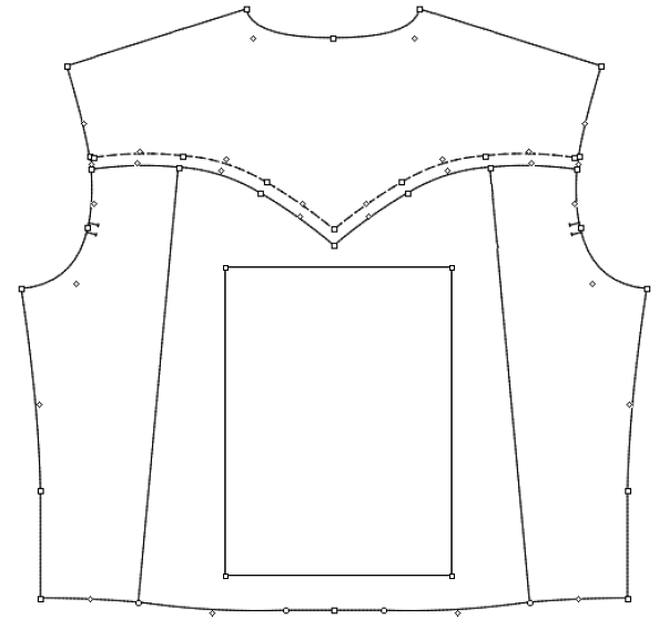
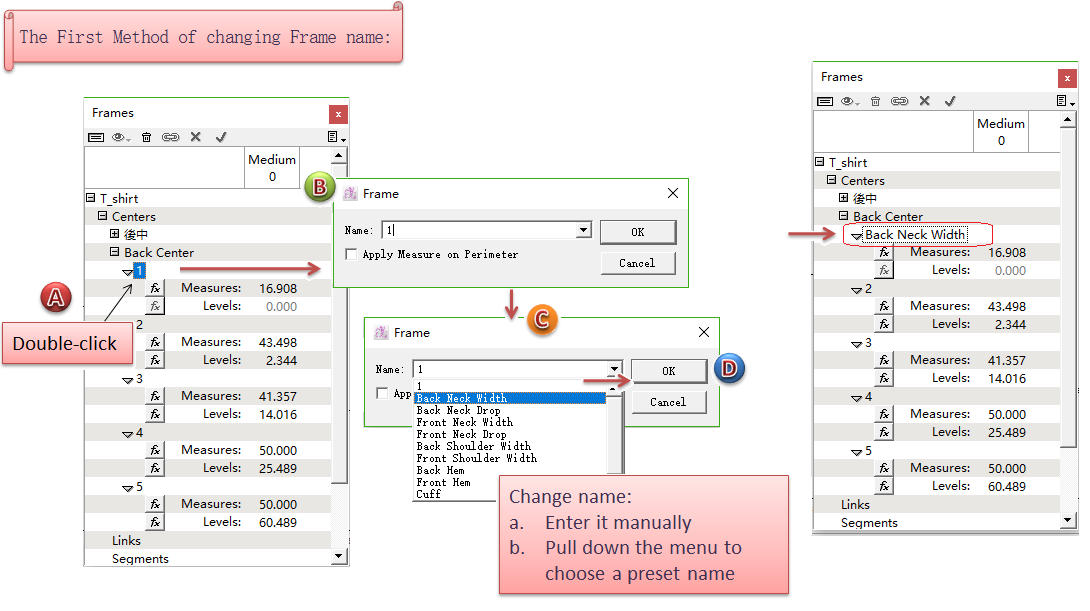
After setting the center segment, it will generate frame segments automatically, and also be named as 1; 2; 3; 4 in order according to the sequence of clicking two reference points (e.g.Reference Point 1 and Reference Point 2 in the image).
備註
The points on the pieces need to be regular points so that it can generate frame segments. If the points is mark point or control point, it can’t generate frame segments. So, if you don’t want to generate frame segment automatically on some position, convert the points into mark point or control point previously. Or without changing the point characteristics, select the desired frame segment and press [Backspace] key to delete.
Example:
Activate the desired piece;
Select
tool;
Click the first reference point and then the second point to set center segment;
Dialog box appears to set center segment, enter name or select the preset name in the pull-down menu;
Click [OK] to set the center segment (pink line), and it generates frame segments (blue line) automatically;
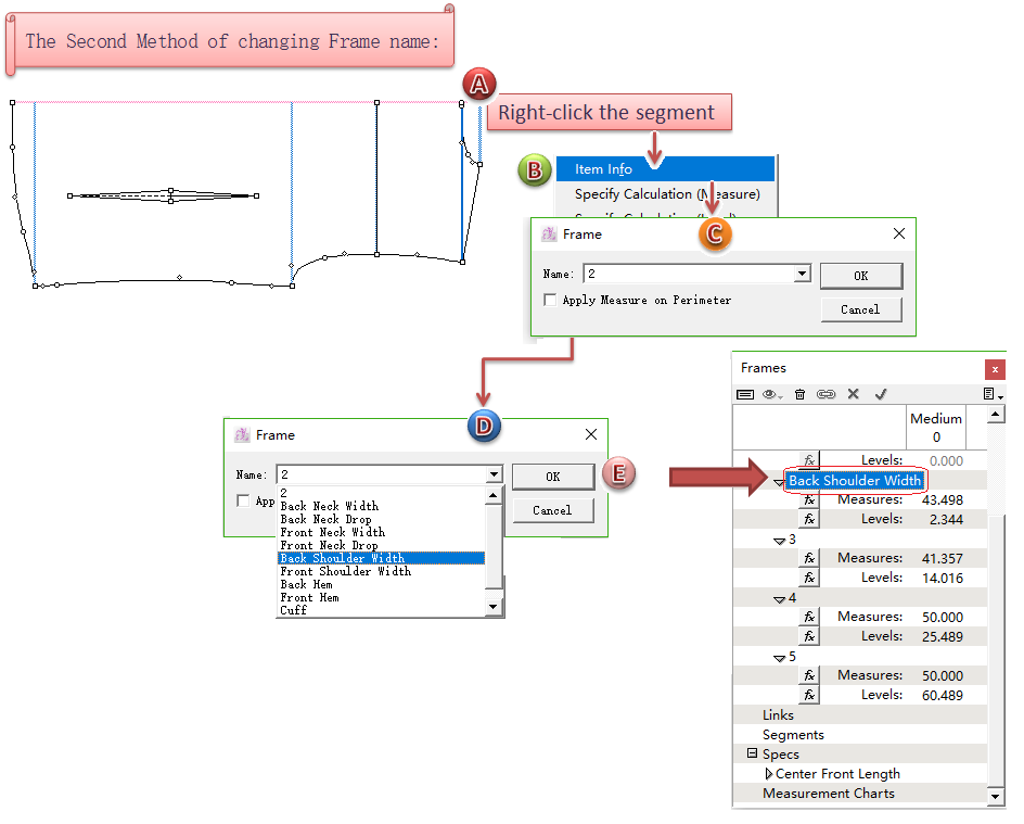
Delete desired segment if needed; Double click the number in the window to open dialog box to change name (First method to change name shown as pic); or right-click the desired frame segment, select [Item Info] in the pull-down menu, change name in the dialog box (Second method to change name shown as pic)
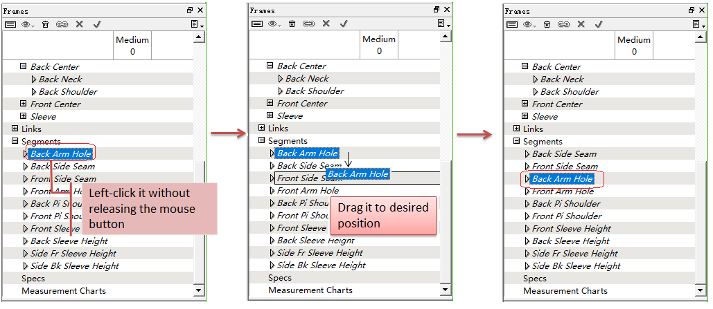
Arrange the Frame items as wish in the Frame window
Drag up or down to relocate the items as wish ((Centers; Links; Segments; Specs; Measurement Charts).
How to do:
Click the desired item without releasing the mouse button;
Drag it to the desired position then release the button.
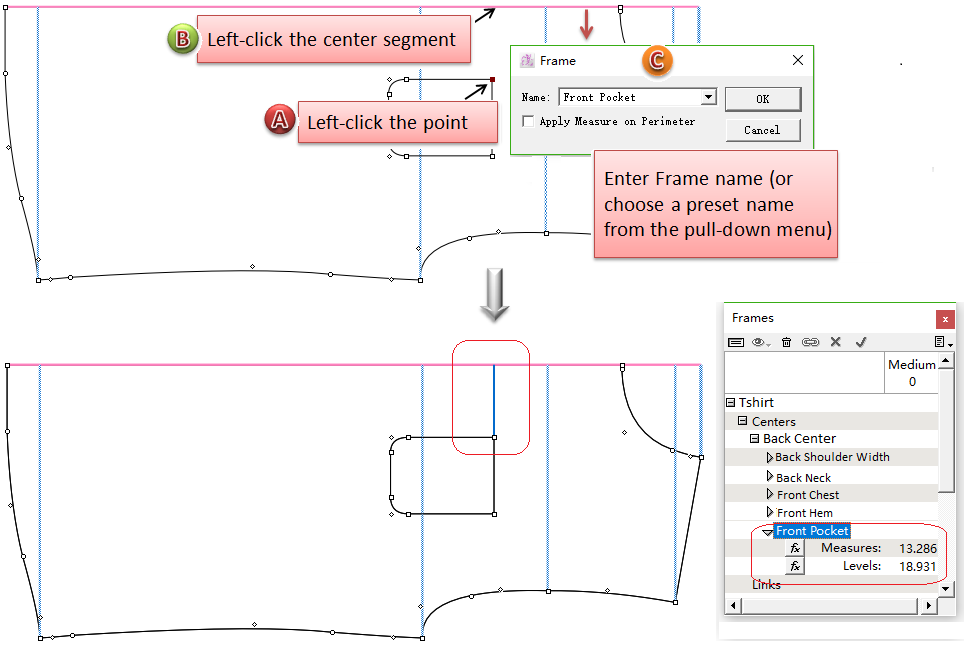
Create internal frame segment
Allow users to build frame segment based on the internal points or segments.
Example shows how to create internal frame segments for the pocket of front piece:
- Activate the desired piece;
- Select
- Click the locating point of the pocket, then click the center segment of the piece (pink line);
- Dialog box appears, enter desired name, click [OK].
[Measurement Charts]
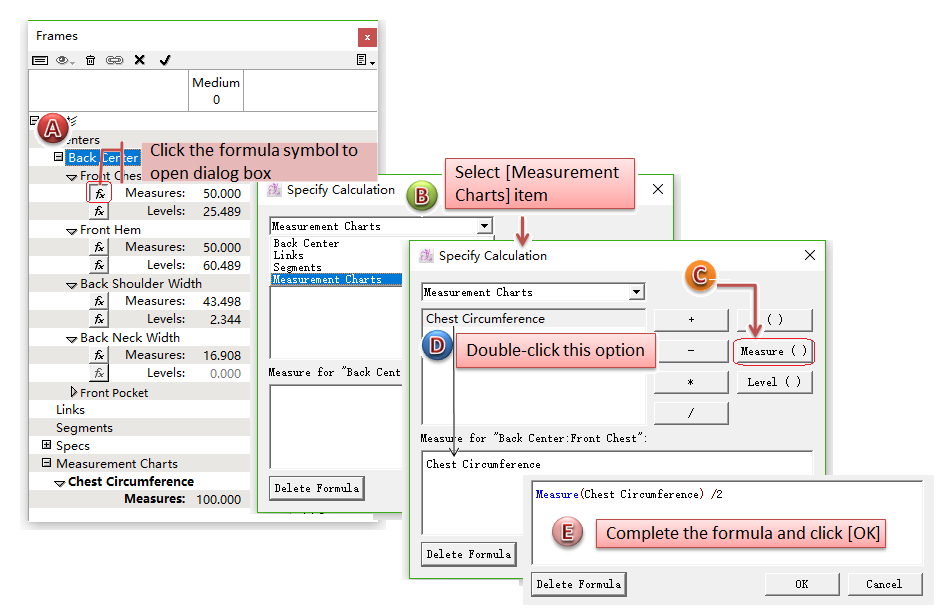
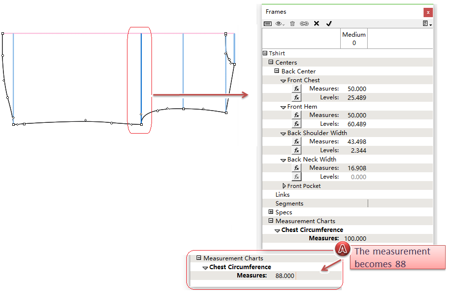
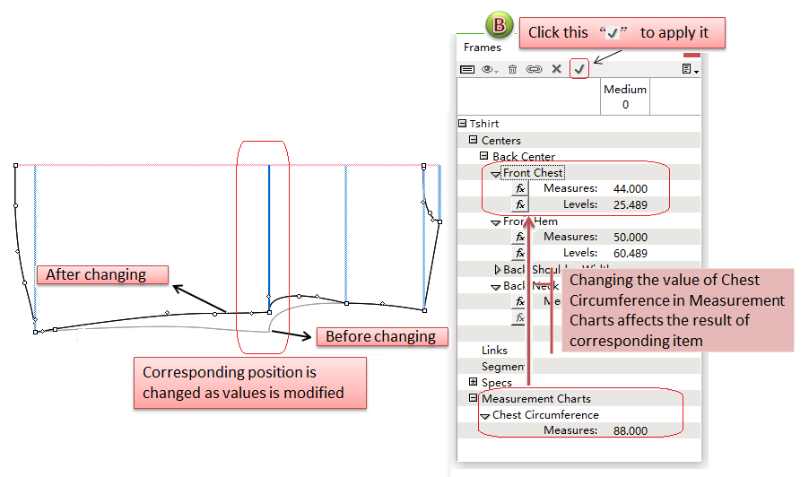
Allow users to enter the existing measurement information into [Measurement Charts], for applying the formulas of corresponding items (Centers; Links; Segments; Specs) while making the frame segments. When users modify the data in [Measurement Charts] item, the corresponding items will also be changed.
For example:
Enter a measurement of chest in [Measurement Charts]:
Apply the corresponding formula for the measurement of chest entered in Step 1:
Modify the value of chest, other items’ values also get changed and the piece is getting changed too.
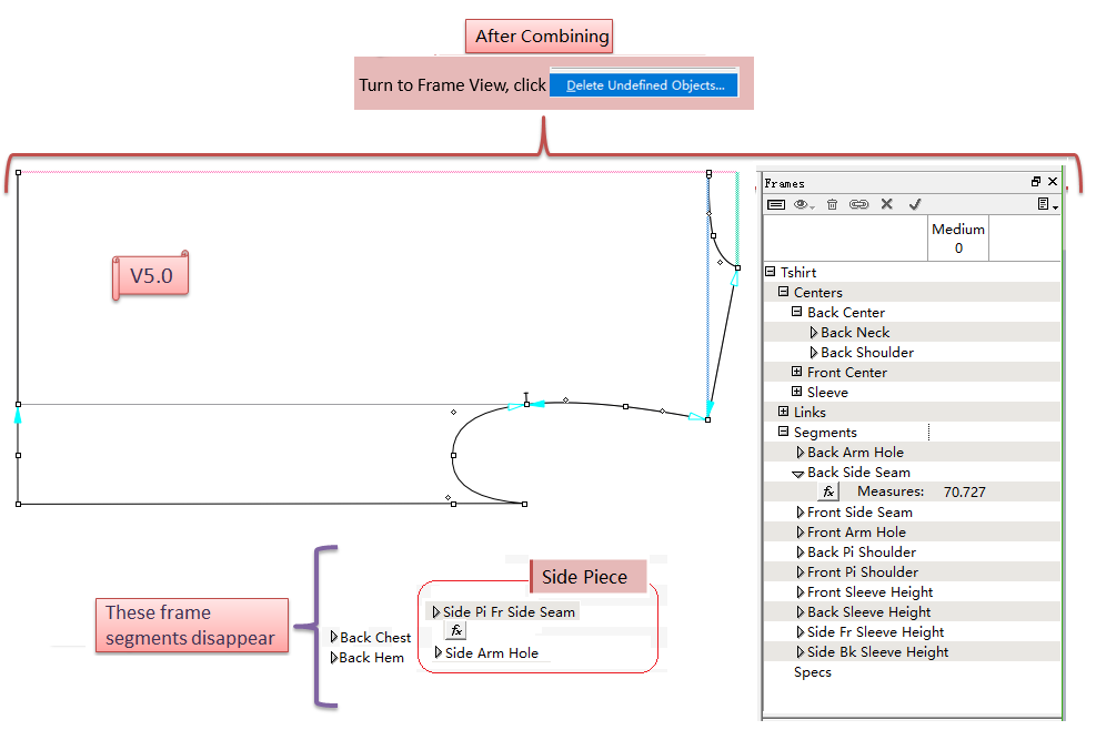
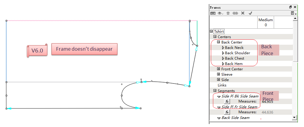
Save the frame segment after splitting or combining the piece(s)
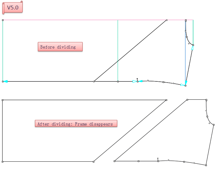
Save frame segments after splitting a piece
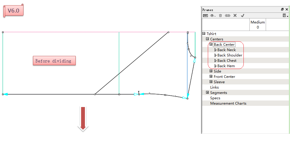
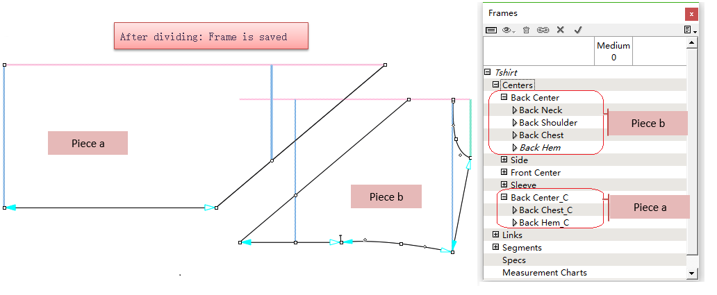
In V5.0, if the piece with frame segments is divided into several pieces, you will found all the frame segments are removed when switch to Frame View. In V6.0, the frame segments will be saved even though the piece is split.
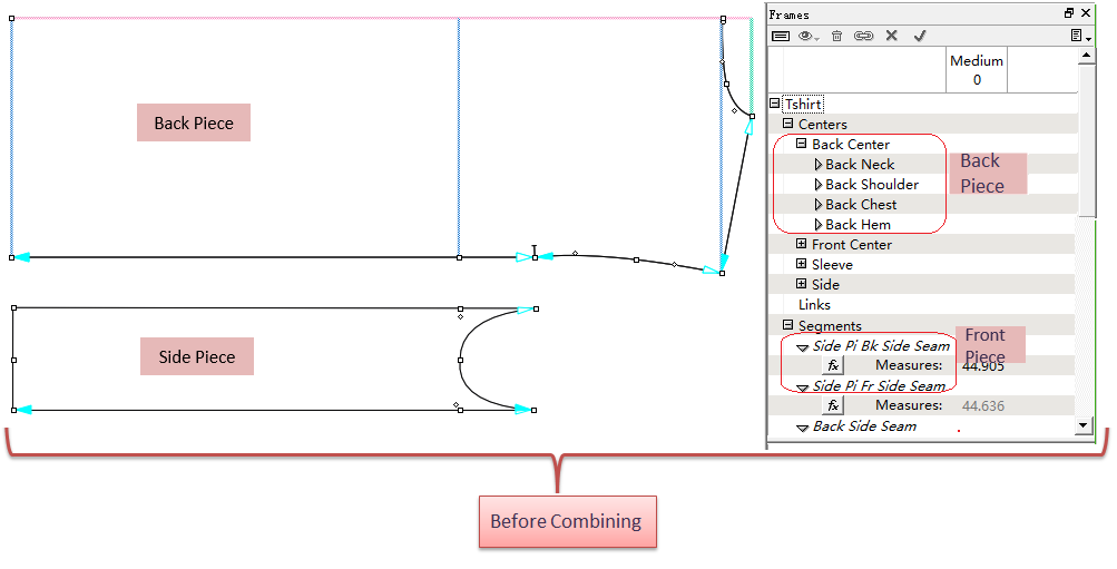
Save frame segments after combining pieces
When the pieces with its own frame segments are combining into one piece, parts of frame segments are removed in V5.0. Now in V6.0, it allows to save all the frame segments.
Simplify Tools
Combine Circle Tool
and Ellipse Tool
into one tool
Circle/Ellipse Tool.
Combine Join Shapes Tool
and Split Shape Tool
int to Join/Split Shapes Tool
.
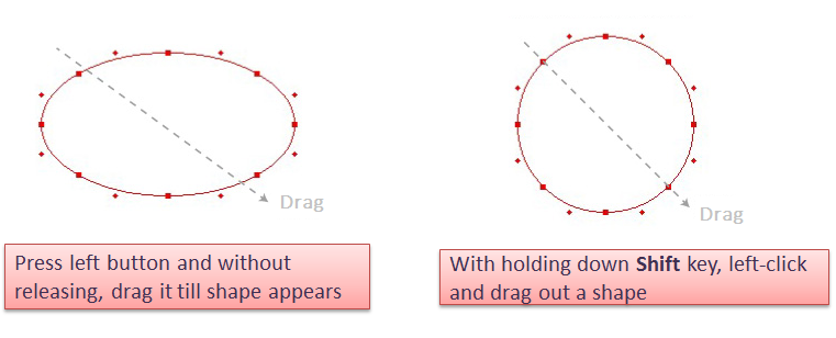
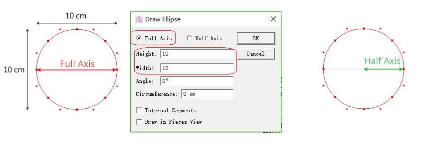
Circle/Ellipse Tool
- Draw circle/ellipse by freehand:
select
select
Draw circle/ellipse by entering value:
Select
- Hold down Alt (Windows) or Option (Mac) key, left-click the desired position. Dialog box appears and enter value.
- Click [OK].
For example, draw a circle with diameter 10cm:
備註
Internal Segment : draw the shape as internal segment of the piece which can be removed.
Draw in Piece : draw the shape as a pattern piece.
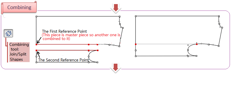
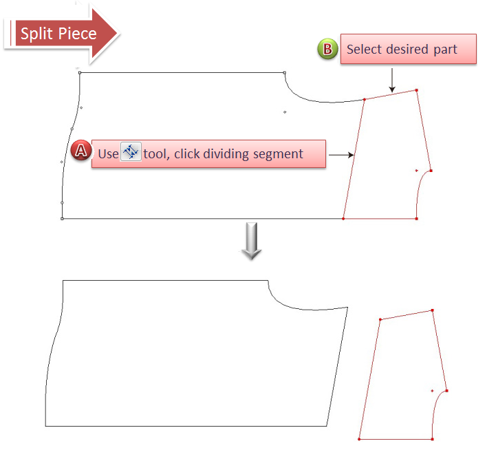
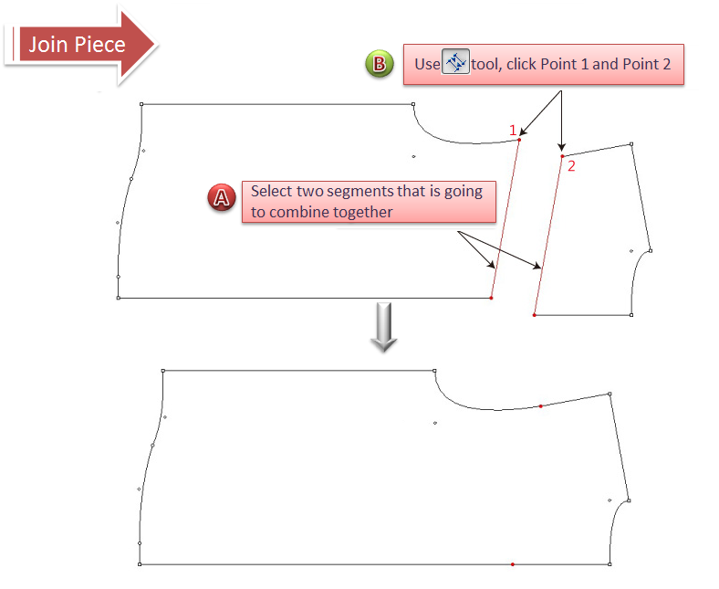
Join/Split Shapes Tool 
Split shapes:
Select the desired part (must be closed polygon);
Select
Click the dividing segment.
Join shapes:
Select two segments that is going to join together;
Select
Click the two points that is going to be connected (If save the joint line, hold down Shift key and click the points).
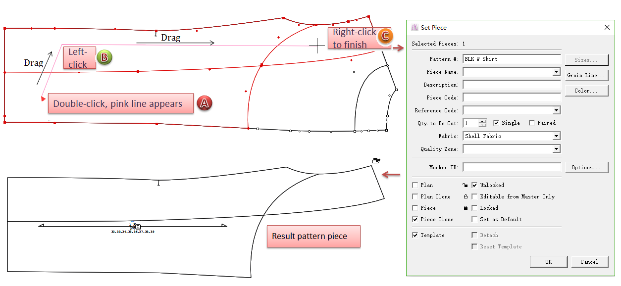
Simplify Operation for Setting Piece
Allow users to set pieces by right-clicking, which improve the efficiency of pattern-making.
How to do:
Select
;
Double left-click on the desired piece, the cursors turns into cross;
Move the cross, a pink guideline appears, move the cursor to desired part and left-click it, then repeat to left-click to select other desired parts;
After select all the desired parts, right-click to finish selecting, the dialog box appears. Set the piece info.
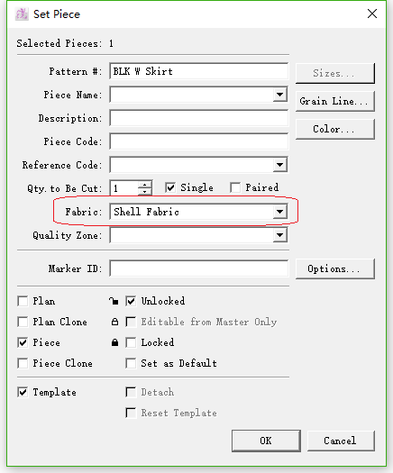
Add Memory Function for [Fabric]
Add memory function for [Fabric] in [Piece Info] dialog box. It will remember the last selected or entered fabric name. It selects the last fabric automatically till you select another one.