[Treatment] Menu provides functions to treat the pieces.
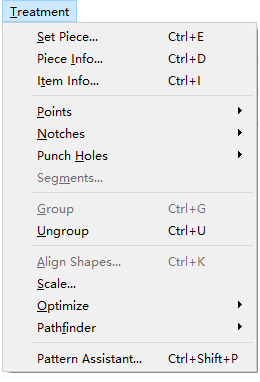
[Set Piece]/[Piece Info]
The dialog boxes of [Set Piece] and [Piece Info] are the same, so we introduce them in the same section.
By [Set Piece], the piece in Plan list are set as pattern pieces shown in Piece list for manufacturing.
Ways of setting piece
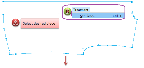
Set piece by [Treatment] Menu:
Select the desired plan piece;
Click [Set Piece] item in [Treatment] Menu;
Enter piece information in the dialog box, such as piece name, piece code and frabic;
Click [OK] button to finish setting.
Double-click to select desired plan piece then right-click it to open [Set Piece] dialog box:
Select
tool;
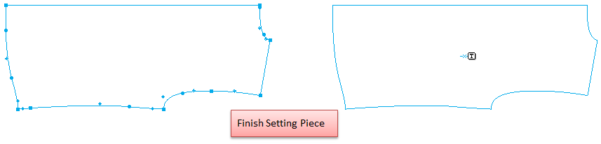
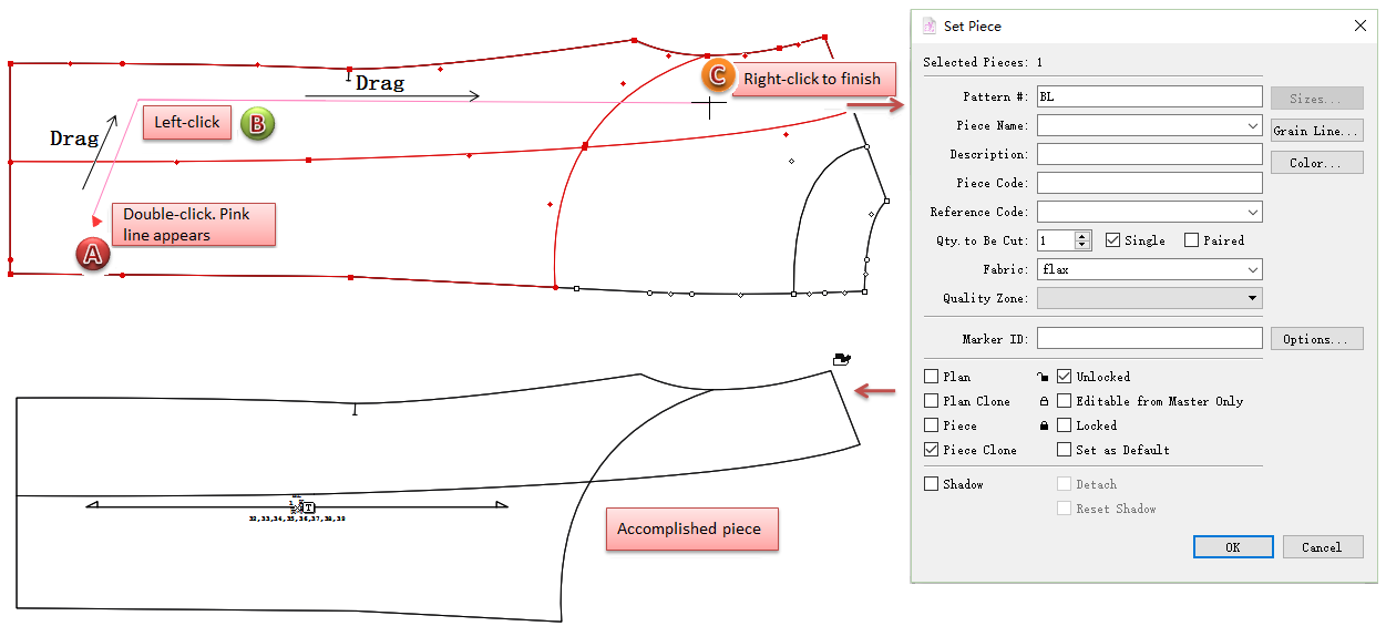
Double-click on desired piece, the cursor turns into a cross +;
Then move the cursor, a pink guideline appears. Move the pink line to desired part and left-click it to select, repeat this step till finish selecting desired parts;
Right-click once and the [Set Piece] Dialog Box appears, enter piece information and click [OK].
New in V7.0
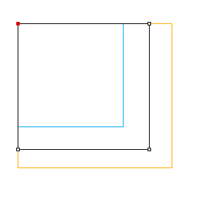
Double-click to extract piece
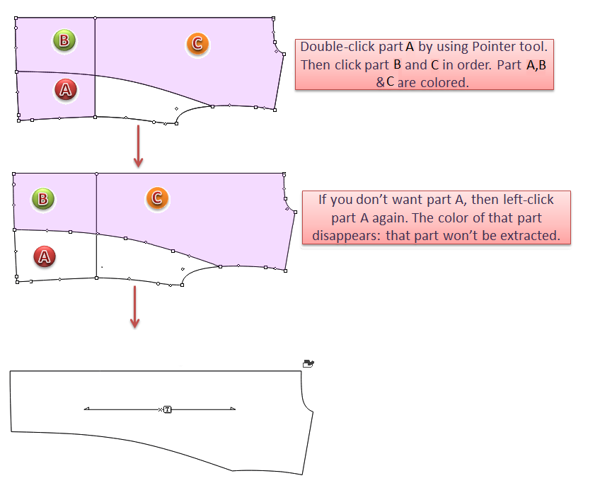
Double-click to start to extract the part of the piece that users wish. The selected part(s) will be colored. Users can undo the former step.
Select
Pointer tool, double-click the target. The part extracted is colored. Then left-click the desired parts that are divided by lines. Left-click the colored part again to undo. Finish extracting by right-clicking.
Extract the internal segment if needed while extracting
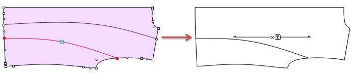
When you are extracting the part of piece, you can also left-click to select or unselect the internal segment(s) with holding down the Shift key.
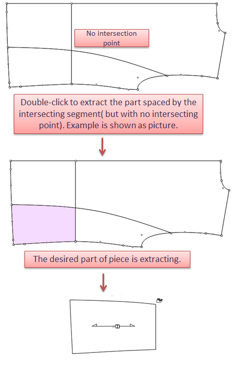
Extract the part of piece even though there is no intersection point on the intersecting lines
In old version of the software, users need to add intersecting point(s) manually so that the desired part(s) can be extracted. Now, in version 7.0, you can extract the part you want directly.
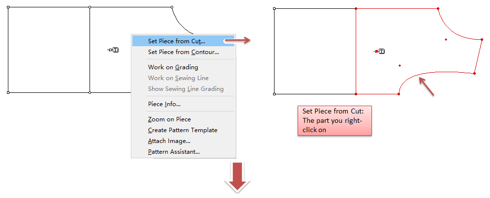
Set piece by right-click menu:
Right-click the desired piece or element, menu appears, select [Set Piece from Cut]:
The dialog box opens. Enter piece info:
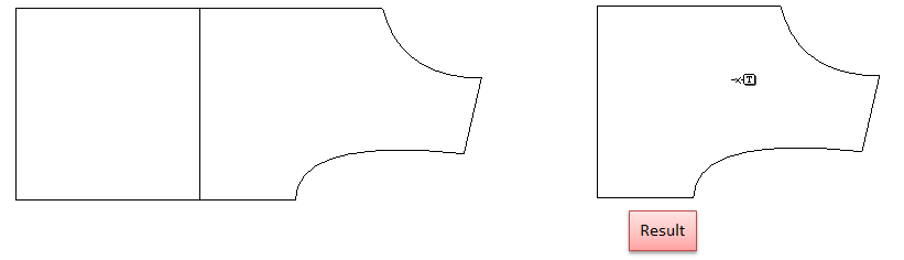
Click [OK] button:
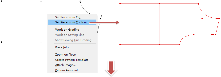
Or select [Set Piece from Contour]:
The dialog box opens. Enter piece info:
Click [OK] button:
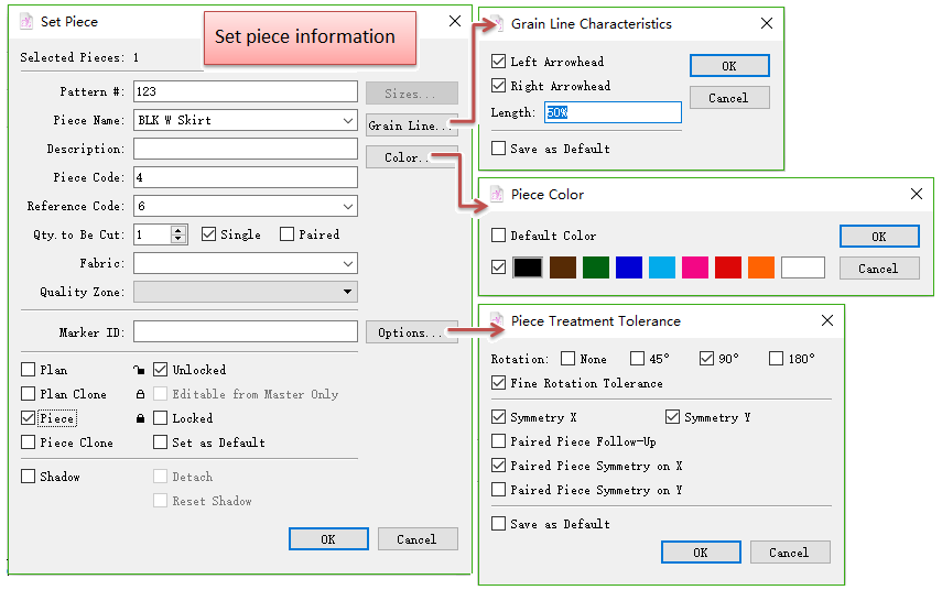
[Set Piece]/[Piece Info] Dialog Box
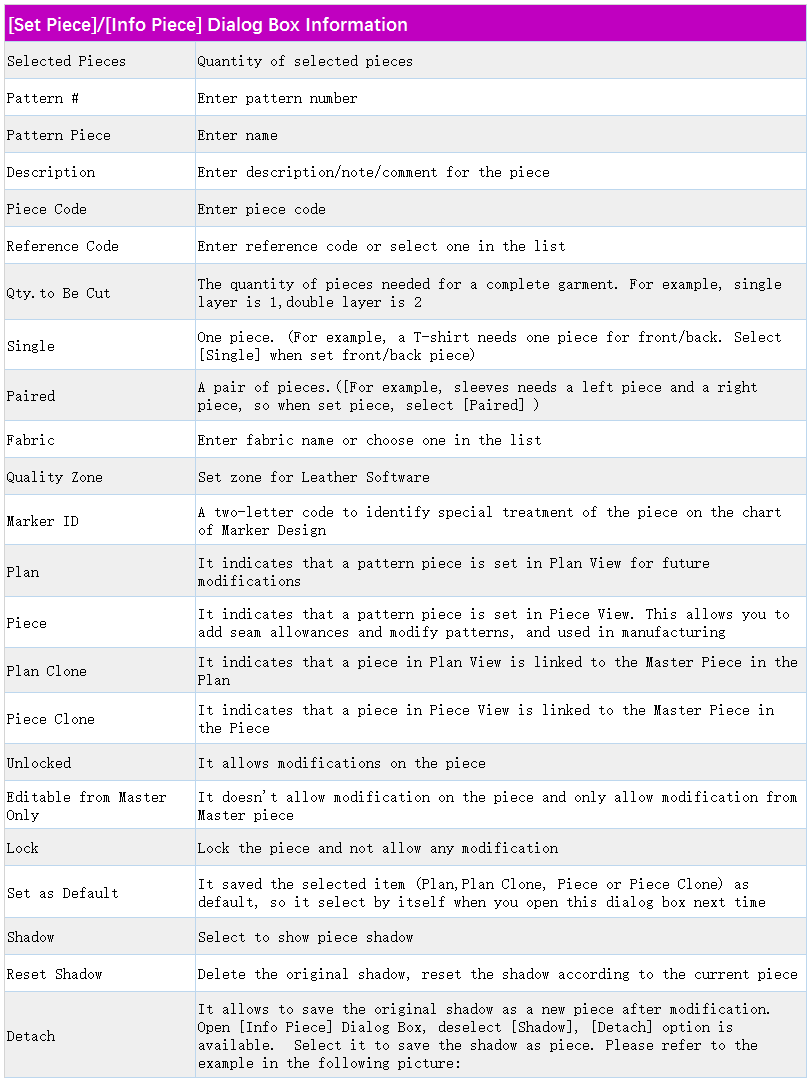
Item Info
Allows user to obtain/edit selected element information, such as mirror, dart, shirring, pleat, seam allowance and seam corner.
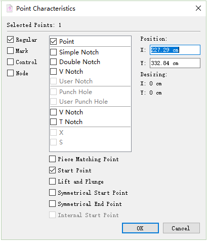
Point Characteristics
Select the point, select [Item Info] in [Treatment] Menu. Point Characteristics Dialog Box appears:
Check or modify the point information in the dialog box.
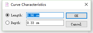
Curve Characteristics
Select the curve, then select [Item Info] in [Treatment] Menu. Curve Characteristics Dialog Box appears:
Change the length or depth value to change the shape.
Note
For more information about curve, please refer to Chapter 3, Curve Tool.
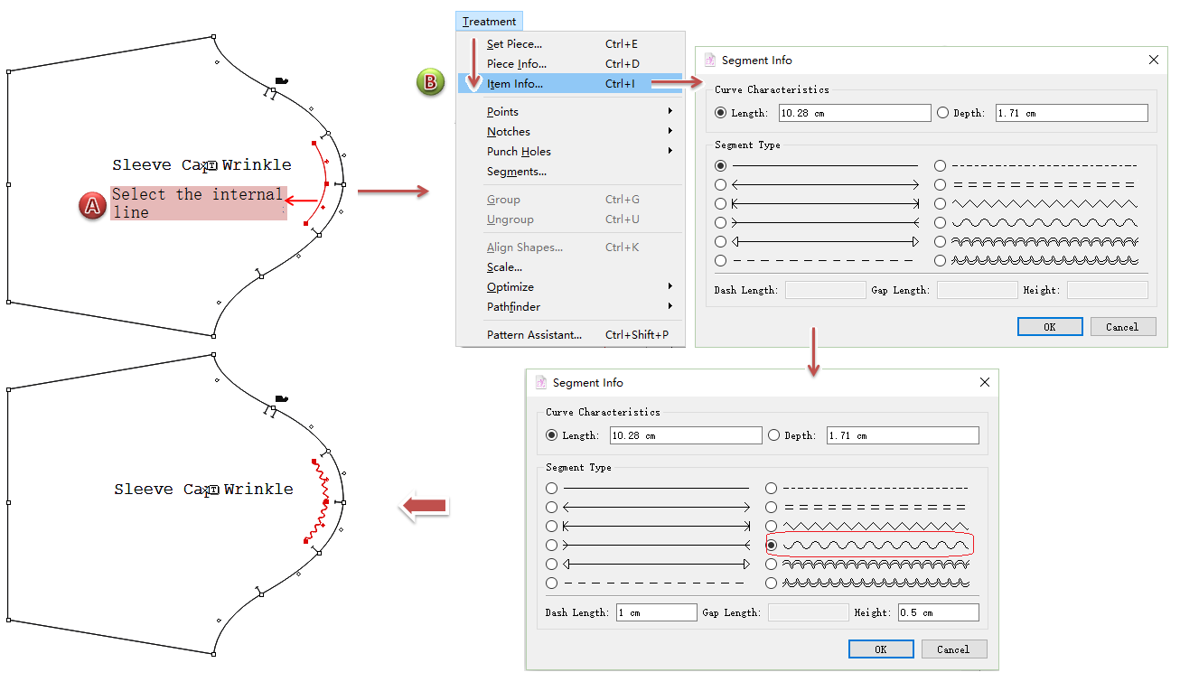
Segment Types
New in V7.0
Allow user to modify the selected internal segment type in [Segment Type] Dialog Box from Menu [Treatment] - [Item Info].
Note
if the selected internal segment is a curve, the dialog box also shows the curve characteristcs. Modify the length and depth as required.
Note
For obtaining the previous way to open [Segment Type] Dialog Box, please refer to the following introduction of [Segment…].
Dart Characteristics
Select the dart, then select [Item Info] in [Treatment] Menu. Dart Characteristics Dialog Box appears:
Change the values to modify the dart shape.
Note
For more information about dart, please refer to Chapter 3, Dart Tool.
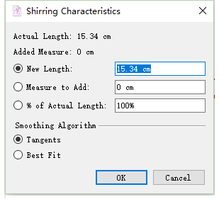
Shirring Characteristics
Select the shirring, then select [Item Info] in [Treatment] Menu. Shirring Characteristics Dialog Box appears:
Change the values to modify the shirring.
Note
For more information about dart, please refer to Chapter 3, Shirring Tool.
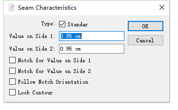
Seam Characteristics
Select the seam allowance, then select [Item Info] in [Treatment] Menu. Seam Characteristics Dialog Box appears:
Change the values to modify the seam allowance.
Note
For more information about dart, please refer to Chapter 3, Seam Allowance Tool.
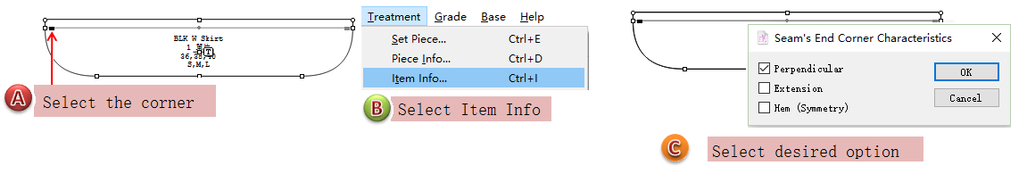
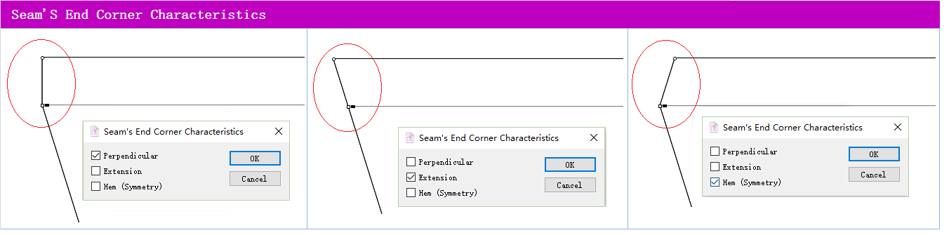
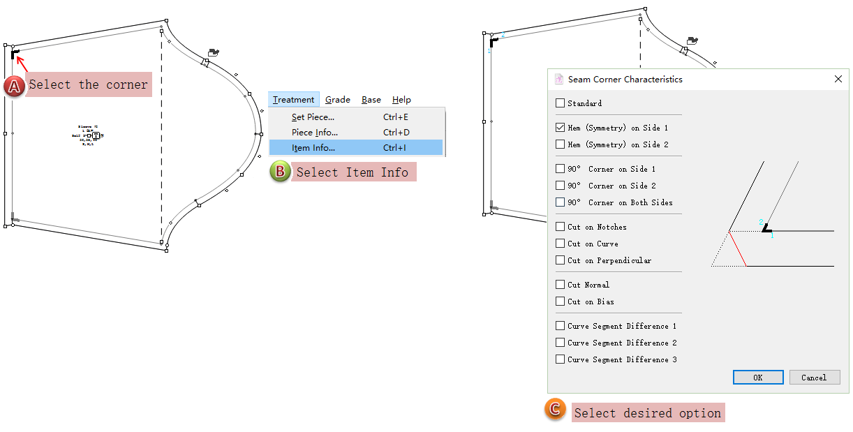
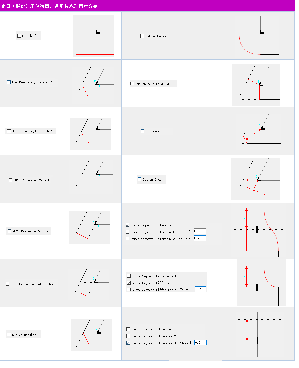
Seam Corner Characteristics
Select the seam corner, then select [Item Info] in [Treatment] Menu. Seam Corner Characteristics Dialog Box appears:
Note
For more information about seam corner, please refer to Chapter 3, Seam Corner Tool.
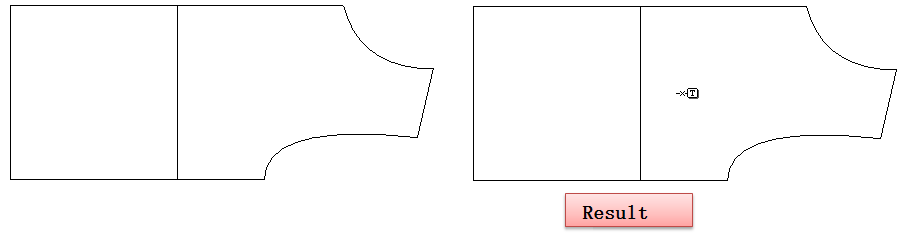
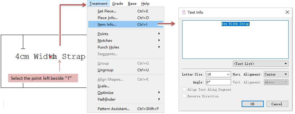
Text Info
Select the point right beside the “T” symbol, then select [Item Info] in [Treatment] Menu. Tex Info Dialog Box appears:
Note
For more information about text info, please refer to Chapter 3, Text Tool.
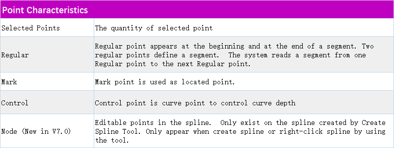
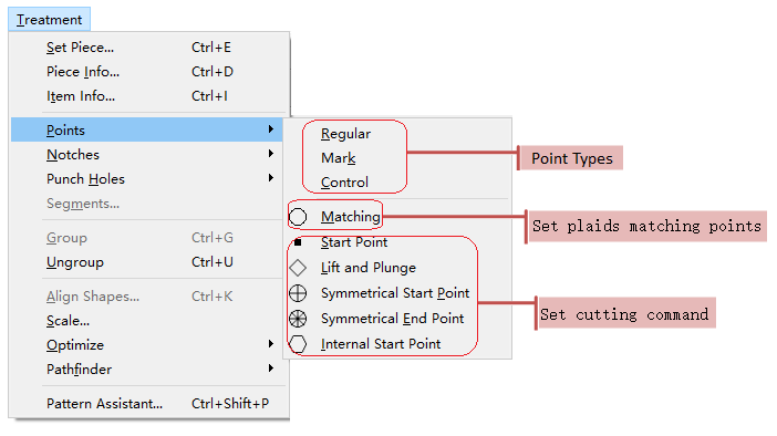
Points
Allow user to modify the point type (Regular, Mark or Control); set matching points for plaids matching in nesting; or preset the cutting command on the points for pattern-making and manufacturing.
Note
User can change the point types in Plan View or Piece View; however, the cutting command on the points can be preset in Piece View only.
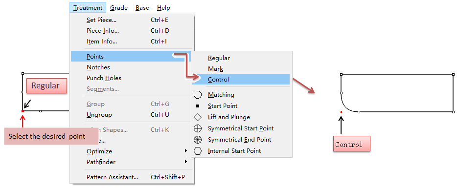
How to change point type
Take changing a regular point into a control point as an example:
Select the regular point;
Click Menu [Treatment] - [Point], and select control point
Note
For more information about points, please refer to Chapter 1.
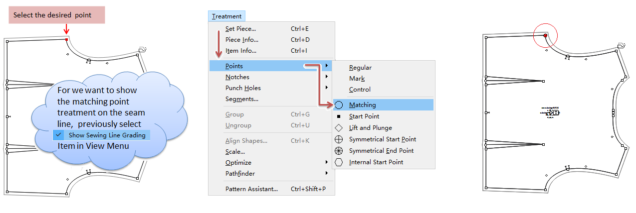
How to set matching point
Set a point as a matching point for plaids matching in nesting.
Select the point;
Select Menu [Treatment] - [Point] - [Matching].
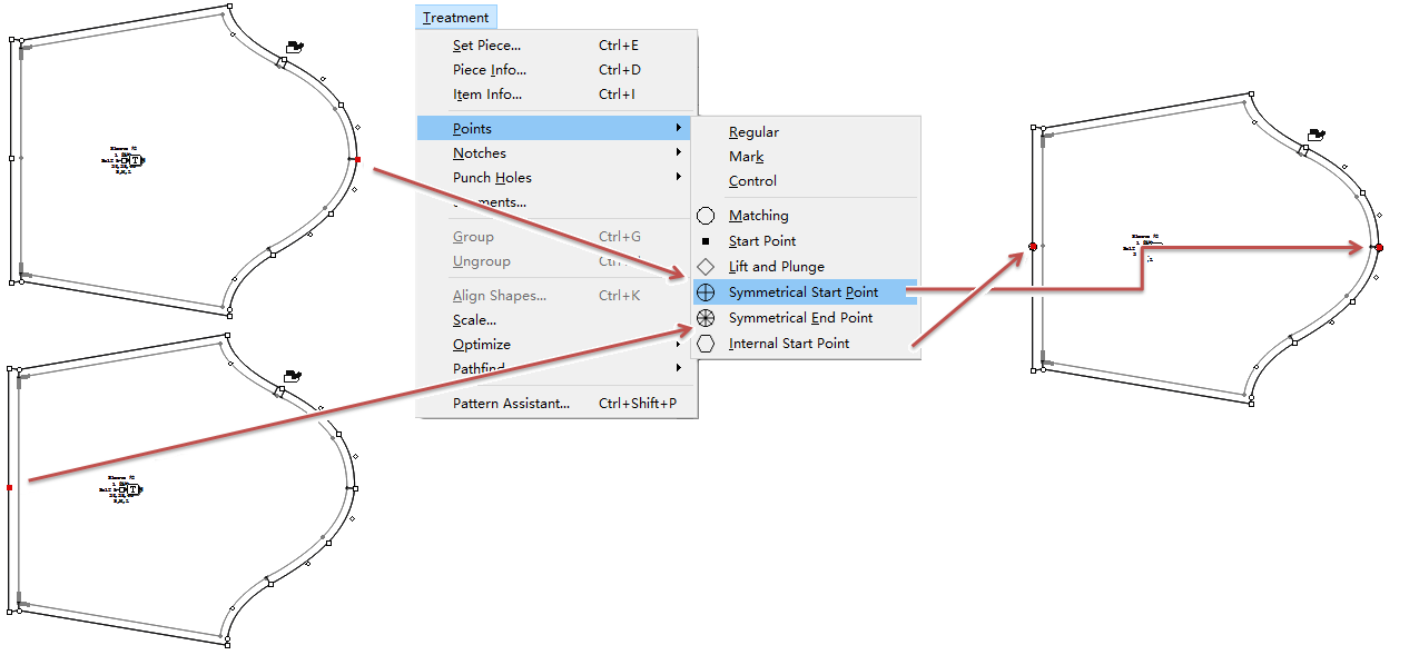
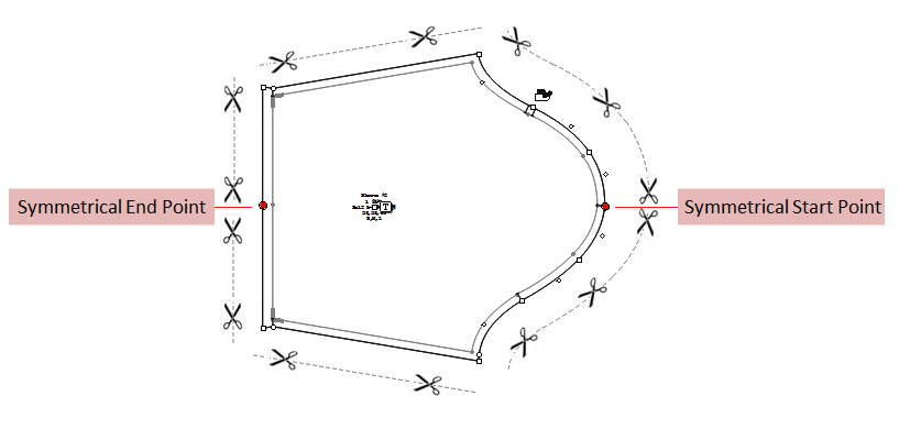
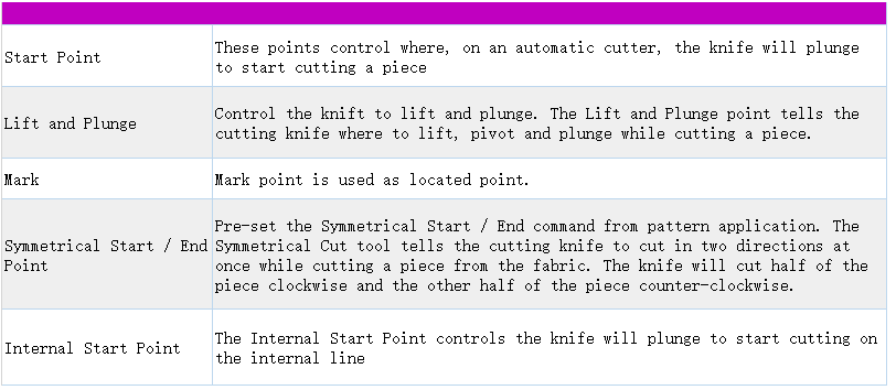
Preset cutting command on the point
Select the point (must be in Piece View)
Click [Treatment]-[Point], and select desired command item
Like: Symmetrical Start Point and Symmetrical End Point:
After setting the points, the piece will be cut as the following picture shown:
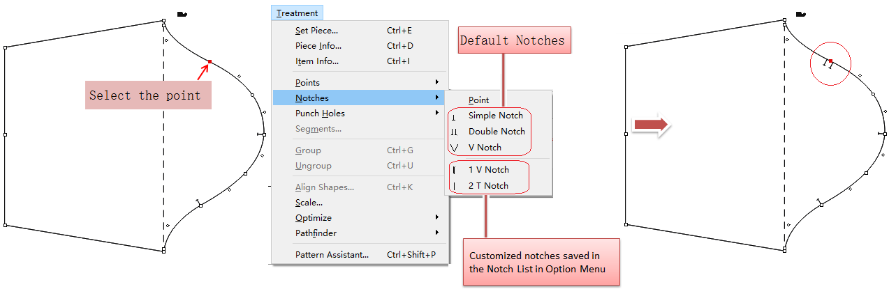
Notch
PAD System™ offers three types of Notches by default: Simple Notch, Double Notch and V Notch. Find them in [Notch] item in the Treatment Menu. User also can use customized notch pre-saved in the [Notch List].
How to add new notch:
Select desired point in the piece;
Note
The point menu is unavailable and in gray if user doesn’t select a point.
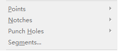
Select [Notch] item in [Treatment] Menu, choose a notch in the list.
If you want to revert the notch to a point, select Point in the same menu.
Note
For more information about customizing notches, please refer to the introduction of [View] Menu [Notch List].
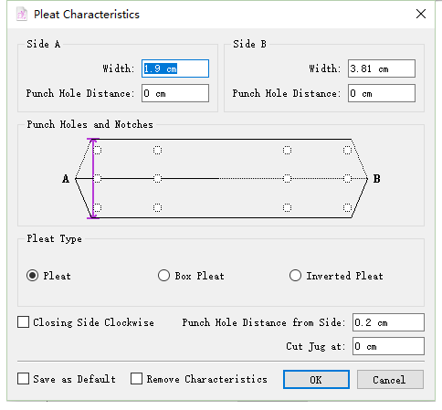
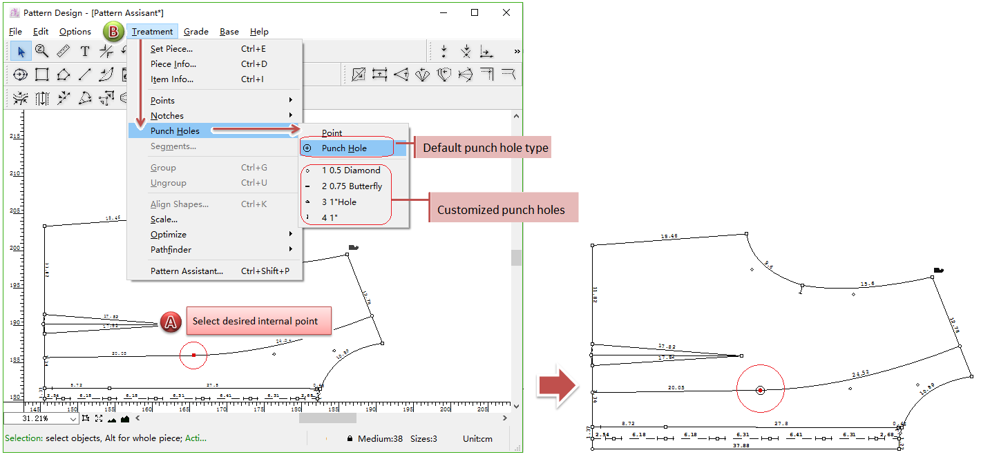
Punch Holes
PAD System™ offers one type of Punch Hole by default:
. This function only works on the internal points. User also can use customized punch holes pre-saved in the [Punch Hole List].
How to add punch hole:
Select the internal point;
Select desired punch hole type in [Punch Holes] item in [Treatment] Menu:
Note
For more information about customizing punch holes, please refer to the introduction of [View] Menu - [Punch Hole List].
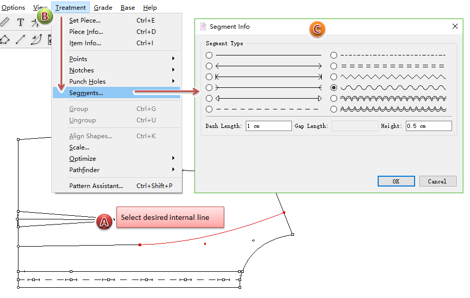
Segment…
The Segment type dialog box enables you to edit the appearance of an internal segment.
Note
If the selected segment is a curve, the dialog box includes curve characteristcs. User can modify the length and depth values.
How to change segment type:
Select an internal segment;
Select [Treatment] Menu - [Segment…], the dialog box appears;
Select desired segment tpye, or change the value;
Click [OK] button to execute.
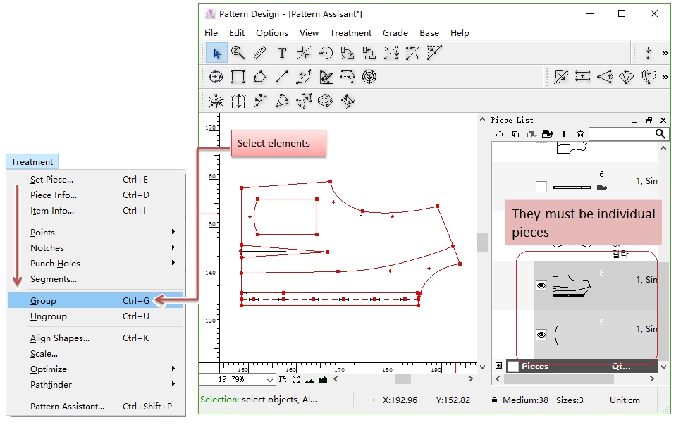
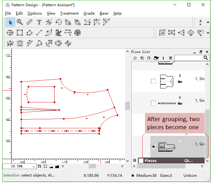
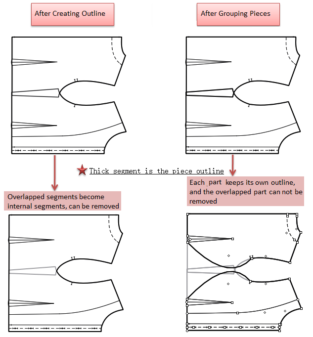
Group/Ungroup
Allow user to group selected elements together so that they are selected as if they were one element. (That means: Group two individual pieces all in Plan/Piece View as one element. For example, the segment doesn’t attach to the piece because the piece wasn’t activated before drawing the segment. They are two individual elements. So we need to group them together); oppositely, user can ungroup the element.
How to group elements
Select the elements;
Select [Group] item in [Treatment] Menu;
Elements are grouped together.
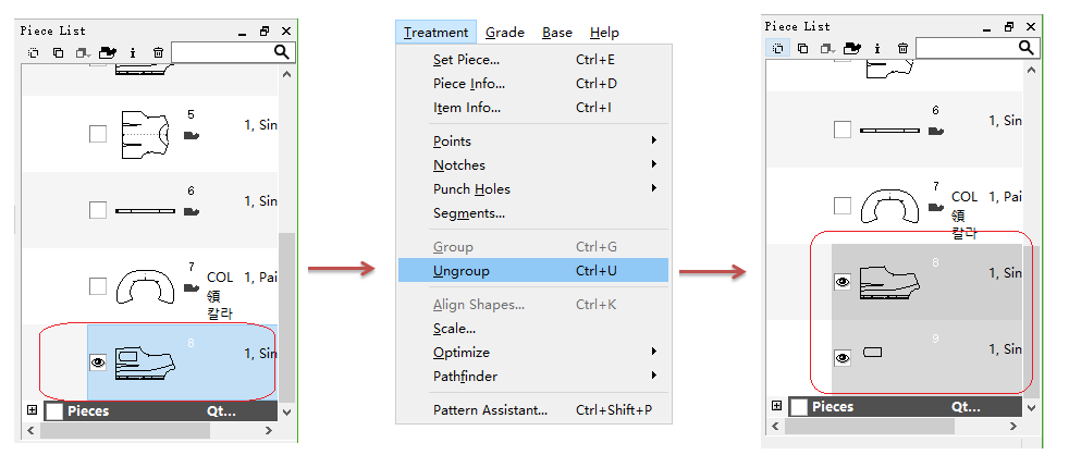
How to ungroup
Repeat the steps above but select [Ungroup] item.
In addition to entire piece, user can also group segments, points and so on.
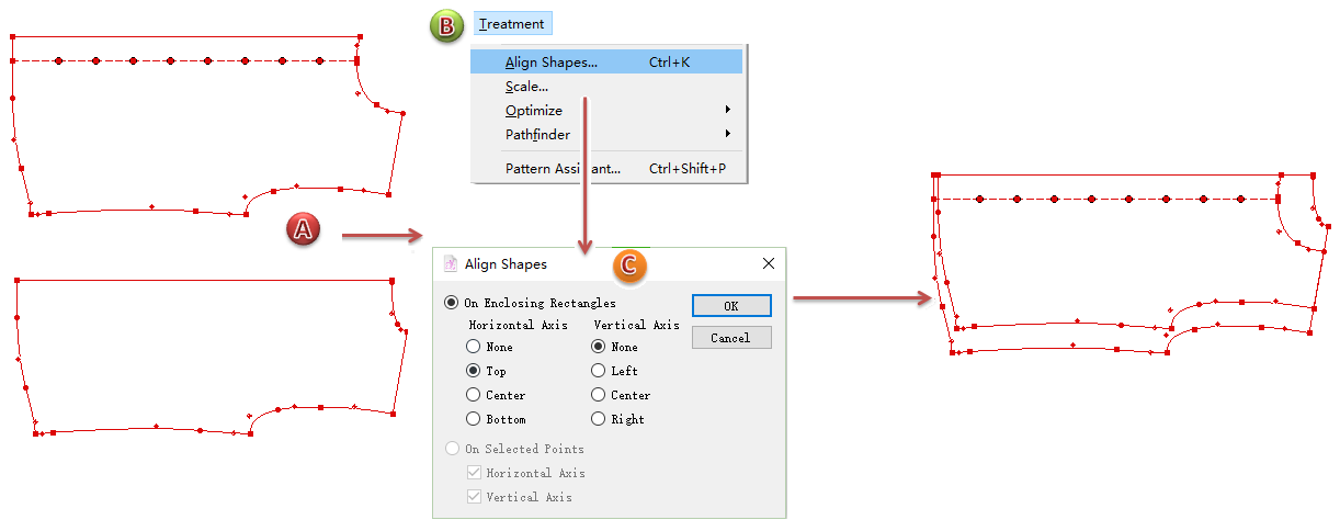
Align Shapes
Allow user to align the selected pieces.
Align on Enclosing Rectangles
Select the desired pieces;
Select [Align Shapes] item;
Select desired option in the dialog box, then click [OK] button.
Align on Selected Points
Select the desired points in the piece;
Select [Align Shapes] item;
Select desired option in the dialog box, then click [OK] button.

Scale
Allow user to scale the selected pieces.
Select the piece, click Menu [Treatment] - [Scale]. The dialog box opens:
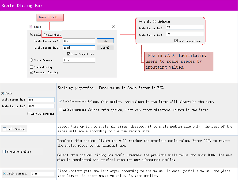
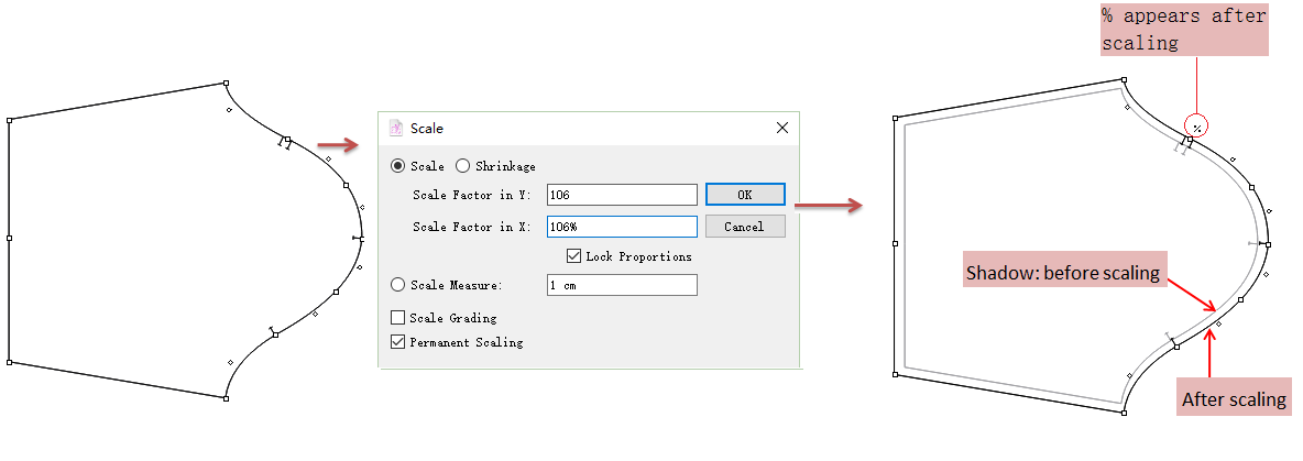
Scale Proportion
Select the piece (or activate it);
Click Menu [Treatment] - [Scale];
Enter proportion in dialog box;
Click [OK] button.
Note
The “%” symbol appears on the top right corner of the piece if use Scale or Shringkage function.
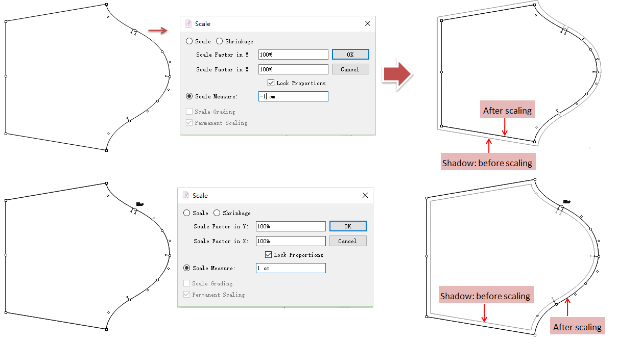
Scale Measure
Enter positive value for enlarging the piece and negative value for reducing the piece.
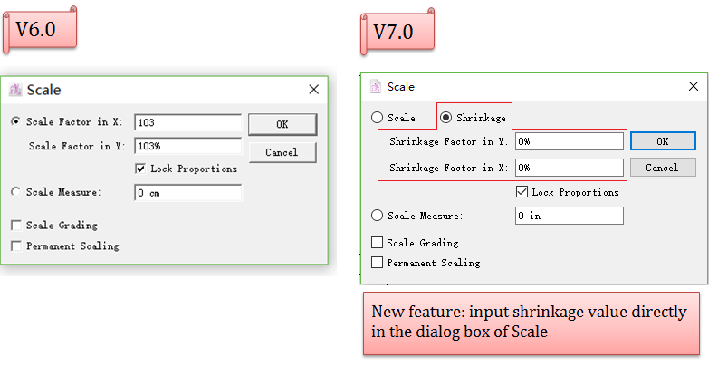
Shrinkage
New in V7.0: facilitating users to scale pieces by inputting values.
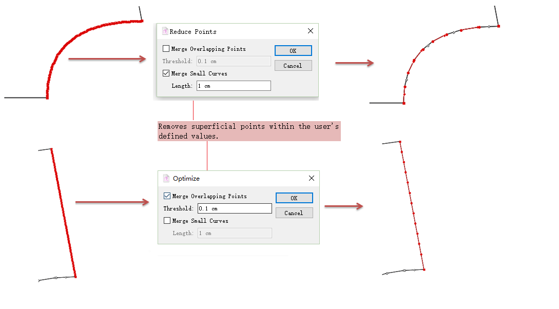
Optimize
Allow user to reduce points, create graded shape and create curve.
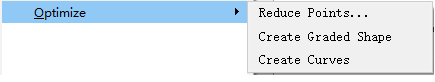
Reduce Points
The Reduce Points… command removes any superficial points on a shape:
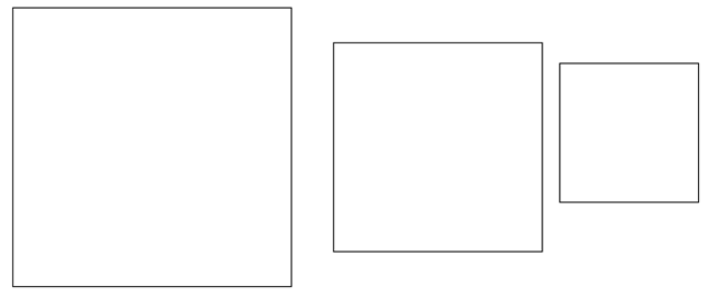
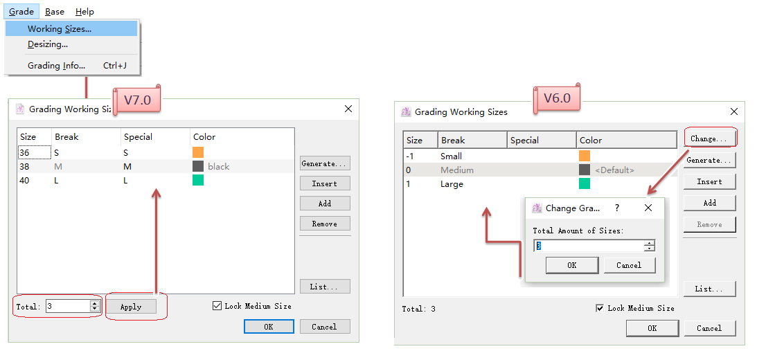
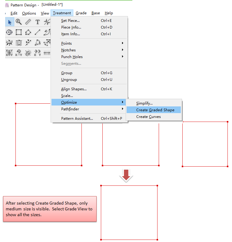
Create Graded Shape
The Create graded shape command creates a graded pattern shape from separate pattern pieces:
As following picture shown, we want to create the graded shape from pieces of S, M and L:
The same number of regular points for each pattern piece
Create sizes:
Select all the pieces, then click Menu [Treatment]-[Optimize]-[Create Graded Shape]:
If you want to finish the graded nest, do as follows:
Use Pointer Tool to select the aligned point on Medium size, in the meanwhile, hold down Ctrl+Alt (Windows) or Command+Option (Macintosh) or Alt+Windows+Ctrl (Linux) key, move the arrow to the Pointer Tool icon, the arrow turns to a cross then click the icon.
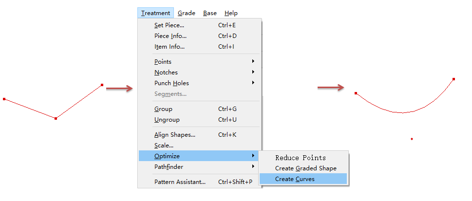
Create Curves
Select the desired elements;
Click Menu [Treatment]-[Optimize]-[Create Curves];
The segment becomes a curve.
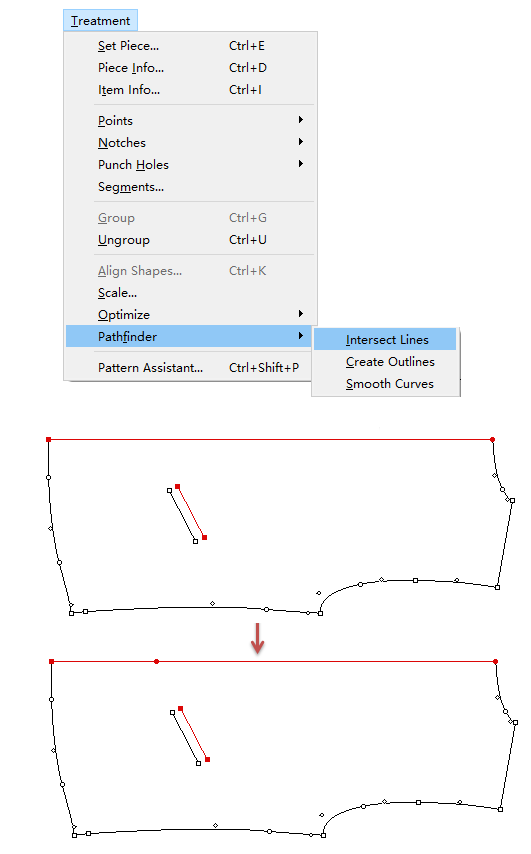
Pathfinder
Allow user to find the intersecting point of two intersecting segments, creates an outline of superimposed shapes and transform corners into smooth edges.
Find Intersection
A point is projected on which the contour and internal is going to intersect:
For example: a point is projected on which the pocket mouth line and side seam segment (they do not touch one another):
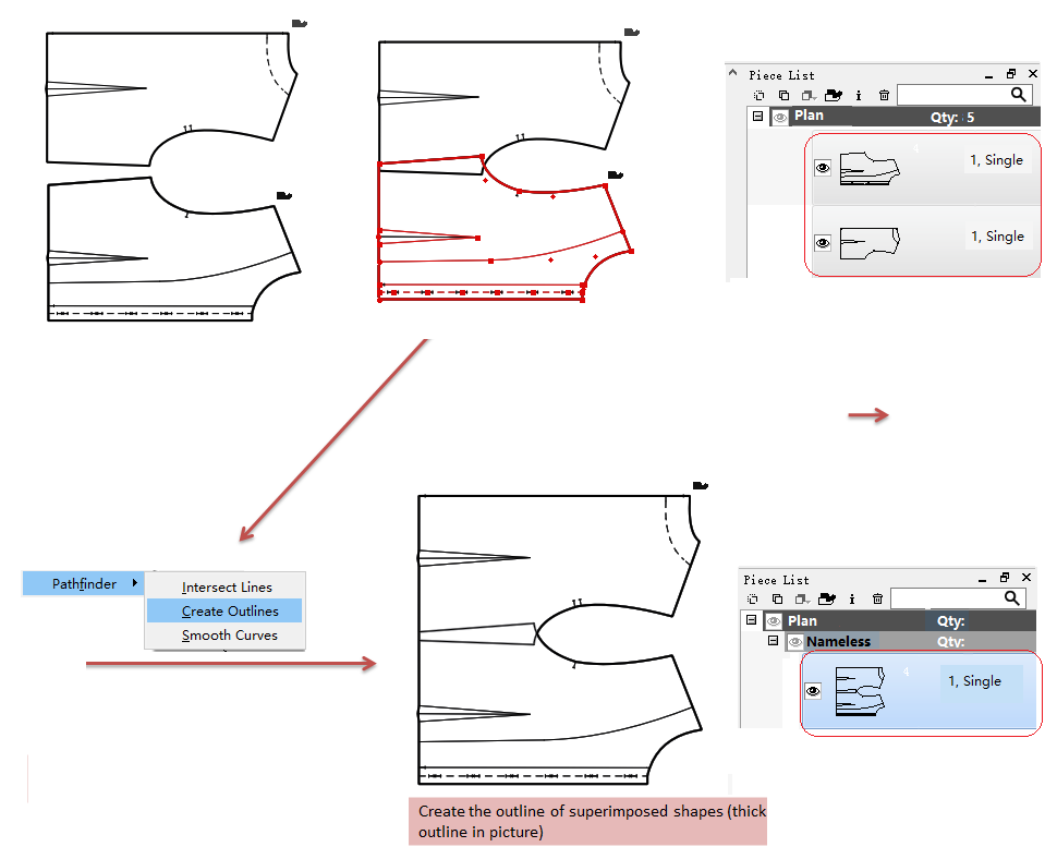
Create Outlines
Unlike Group, Create Outlines is to make the outline of superimposed shapes as new contour, and the elements inside the polygon contour become internal segments, which can be removed.
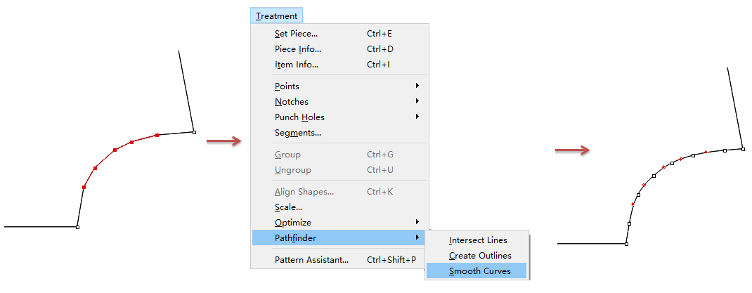
Smooth Curves
Add curve (control) point between every two regular points, to transforms corners and sharp edges into a smooth shape by creating curves.
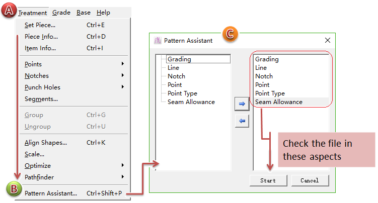
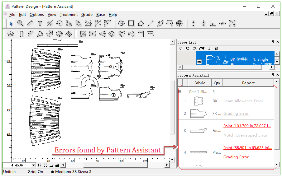
Pattern Assistant
The system will check over the piece file and find out the errors automatically. It shows the error information in detail so that reduces the errors while making pattern pieces.
Finishing drawing the pattern piece(s), users can start [Pattern Assistant] to check if there’s any error in the file before it is sent out to product.
Click Menu [Treatment] then [Pattern Assistant];
[Pattern Assistant] dialog box appears, the system will check over the file in Grading, Segment, Notch, Point, Point Characteristics, Seam Allowance to find out the errors, click [Start] to begin checking.
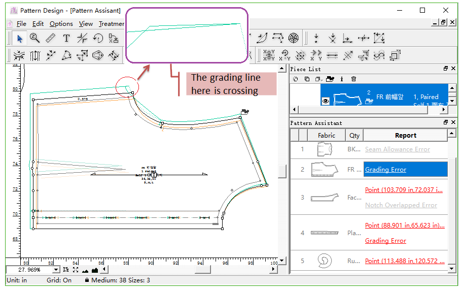
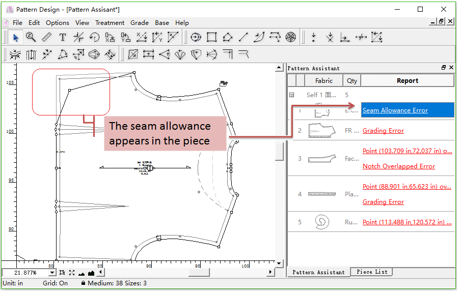
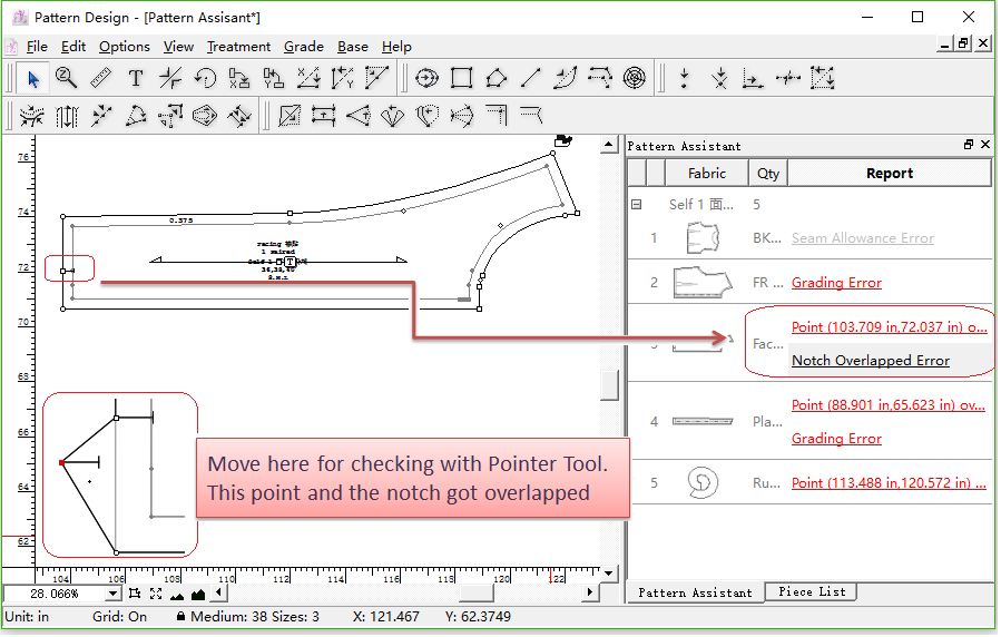
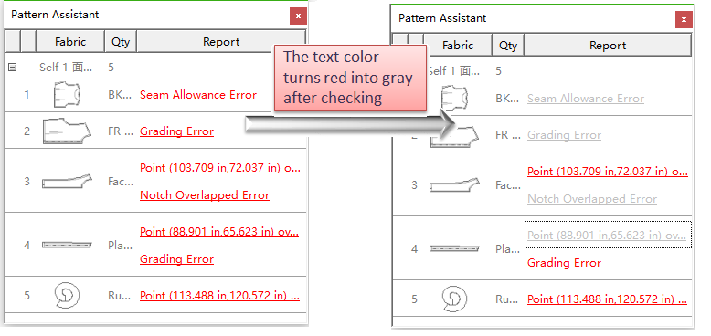
If the system find out any error, it will show them in the floating window in the sidebar of software window.
Click one of the error items in the floating window, the piece with problem will be magnified and viewed in the middle of work area.
Note
If the error information was checked already, the color would turn red into gray.
Check specific piece with [Pattern Assistant] by manual
Right-click the piece need to be checked and click [Pattern Assistant] on the pull-down menu, then repeat the step 2,3 and 4 shown as above to find out the error information.

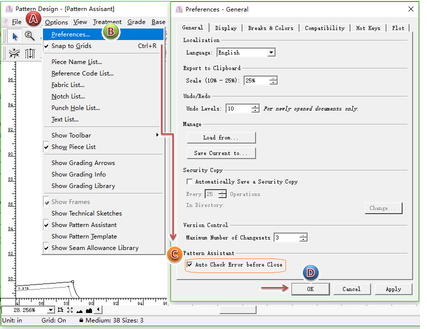
Auto check error before close
Set [Auto Check Error before Close], the software will automatically execute [Pattern Assistant] to check over the file before it is closed.
Picture shows how to set:
Note
You can press Esc key to force to quit this function.