New tool:Create Spline  
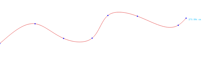
The new tool facilitates users to draw a continuous and accurate spline easily and quickly. Create Spline also allows users to curve a straight line or make a parallel without converting other tools.
Draw continuous spline
To draw a continuous spline without point limitation:
How to do:
Select
Draw a spline by continuous left-clicking on the desired area and right-click to finish drawing.
Note
It will be a straight line if just click two points.
How to edit the spline?
Selectr
Right click the spline to show up all the points
Edit the spline:
3.1 Left click the point (keep hold down and do not release it), drag the point to the desired position; or left click to select the point, and then press the arrows on the keybord to move the point.
3.2 Hold down Alt (Windows) or Option (Macintosh) or Alt+Windows (Linux) key, left click the point which you want to move (keep hold down and do not release it), then move the mouse to edit the spline’s shape.
Snap points by exact value
Allow users to snap the curve points by entering precise value.
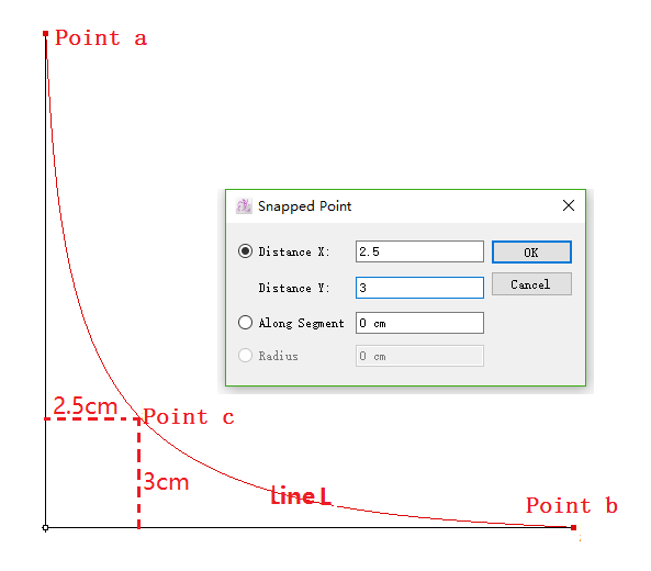
Draw Line L that goes through Point c
How to do:
Select a reference point (like Point a);
Select
Hold down Alt key (Windows) or Option key (Macintosh) and click on the blank space;
Enter 2.5 to Distance X and 3 to Distance Y, click OK;
Point c appears, then connect Point c and Point b by spline.
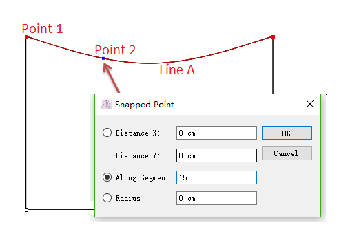
Take Point 1 as reference point, draw Point 2 and the distance between two point along Line A is 3 cm .
Select Line A;
Select
Hold down the Alt key (Windows) or Option key (Macintosh) and left-click Point 1;
Enter 3 cm to Along Segment in the dialog box.
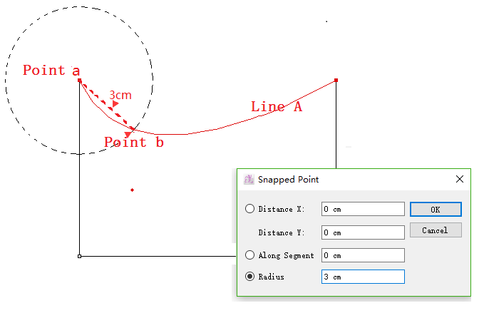
Draw Point b on Line A, and the distance between Point a and Point b is 3 cm:
How to do
Select Line A;
Select
Hold down Alt key (Windows) or Option key (Macintosh) and left-click Point a;
Enter 3 to Radius;
Click OK button.
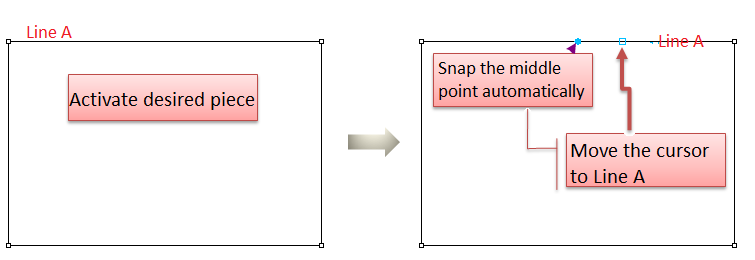
Snap central point
Help users to snap the central point of the selected reference segment.
How to do:
Activate desired piece;
Select
Move the cursor to Line A, the blue point, also the central point of Line A turns up.
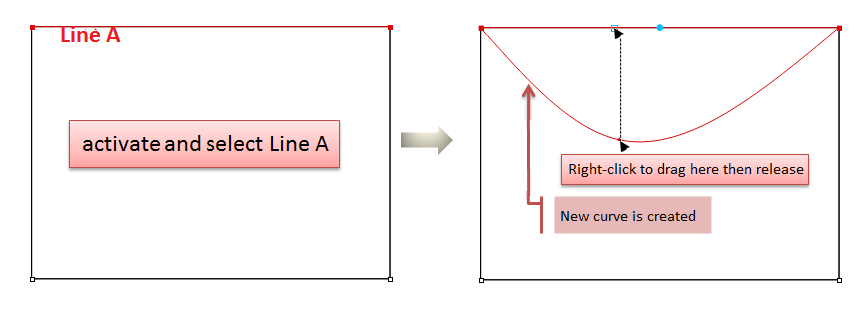
Curve a segment
Right-click to drag the selected straight line into a curve.
How to do:
Activate desired piece, select Line A (your desired segment);
Select
Move your cursor to Line A, right-click to drag it till desired shape.
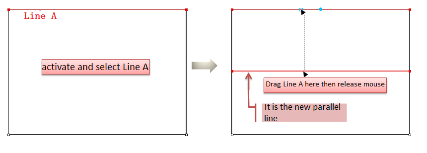
Draw parallel line
Drag the selected spline with left-clicking to draw parallel line.
Activate desired piece, select Line A (your desired segment);
Select
Move your cursor to Line A, left-click to drag it to desired position.
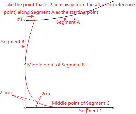
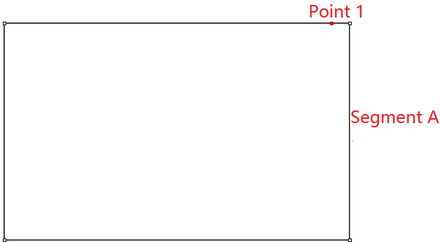
Exercise
For example,
How to do:
Activate the piece and select Segment A;
Select
Hold down the Alt key (Windows) or Option key (Macintosh) and left-click point#1;
Input the values of Along Segment in the dialog box, a point will appear in Segment A and left-click it;
Move the mouse to line B, it will snap the middle point of Segment B automatically;
Left-click the middle point of Segment B;
Hold down the Alt key (Windows) or Option key (Macintosh) and left-click the point#2, input values in Distance X and Distance Y, the point will appear, then left-click it;
Move the mouse to line C, the middle point of Segment B will appear automatically, then left-click it;
Right-click to end drawing.
Note
Press Z key on the keyboard to undo the former point;
To modify the spline, select
Add new node(s): Hold down Shift key, left-click desired location on the spline to add new node;
Remove node(s): Hold down Shift key, left-click the desired node(s) to delete; or hold down Ctrl key (Windows) or Command key (Macintosh) to select all the desired nodes, press Backspace key to delete;
Move nodes to modify spline shape: Left-click to drag the node to desired location; or hold down Ctrl key (Windows) or Command key (Macintosh) to select all the desired nodes, then use arrows key on the keyboard to move them to desired location.
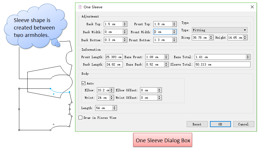
Add One Sleeve
One sleeve will be created according to the armhole contour of the front and back pieces. You can modify shape of the sleeve in the dialog box. One Sleeve helps you to improve the efficiency of making sleeve.
How to do:
Select part of the contour of the armholes from two pieces;
Click Base-One Sleeve;
With holding down the Ctrl key(Windows) or Command key (Mac), left-click to select the armhole of front piece (select more segments with Shift key), then release the Ctrl key(Windows) or Command key (Mac), right-click on any position;
Hold down the Ctrl key(Windows) or Command key (Mac) again and left-click to select the armhole of back piece ( Shift : select more), release the key and right-click on any position. The dialog box appears. Change the value as you wish.

Simplify Some Tools Operation
It simplifies the operation for some tools. Allow users view the value dialog box without using Alt (Windows) or Option (Macintosh) or Alt+Windows (Linux) key. The dialog box shows in the lower-right corner of the cursor, users can enter values directly, which improve the efficiency of making pattern.
The tools are listed as follows:
;
;
;
;
;
;
;
;
;
Now introduce how to use these tools after simplifying the operation.
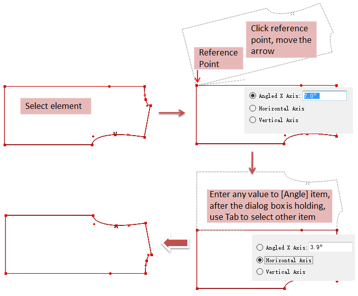
Symmetry Tool 
Select desired element
Select
Click the reference point and move the cursor, dialog appears:
Enter angle value, press Enter key on keyboard to confirm
If want to select [Horizontal Axis] or [Vertical Axis] item, enter any value in [Angle] item, then use Tab key to select. Press Enter key to finish operation
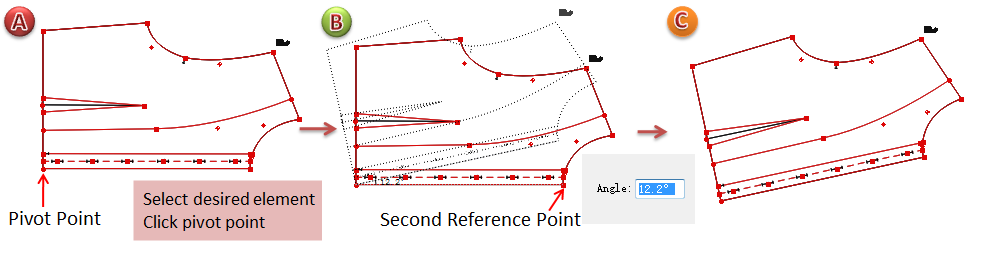
Rotation 
Rotate by using mouse only
Select element
Select
Click the pivot point
Click the second reference point, move the cursor. Meanwhile, the dialog box appears in the lower-right corner, rotation angle and result are shown
Move the cursor to make desired angle, left-click any where to finish operation
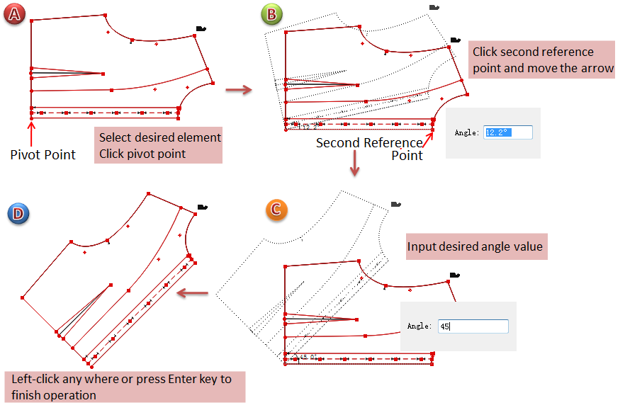
Rotate by entering precise value
Select element
Select
Click the pivot point
Click the second reference point, move the cursor. Meanwhile, the dialog box appears in the lower-right corner, rotation angle and result are shown, users can input desired angle value directly
Left-click any where or press Enter key to finish operation
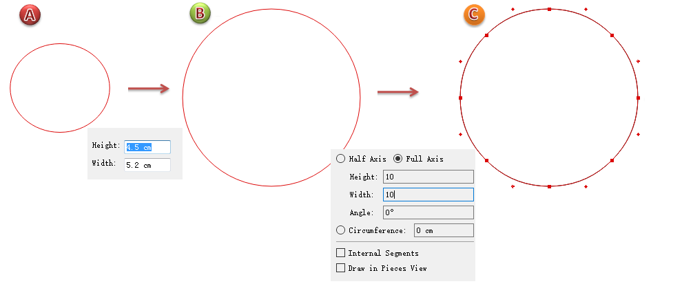
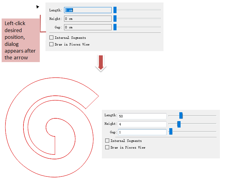
Ellipse/Circle 
For example, to draw a circle with a diameter of 10 cm.
Select
Left-click the desired position then move the cursor, the dialog showing values appears after the cursor
Enter 10 in [Height] item, then the rest of the items in the dialog box appear, then enter value 10 in [Width] item, the circle is created
Left-click any where or press Enter key to finish operation
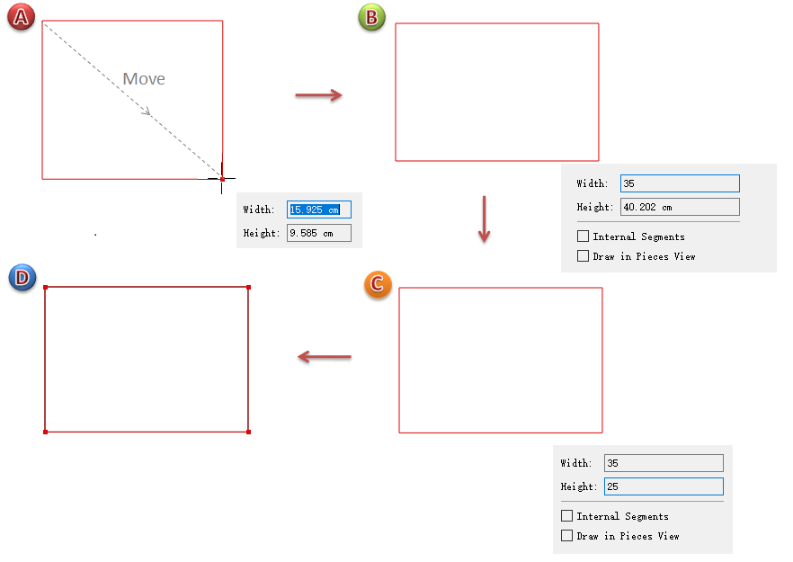
Rectangle 
For example, to draw a rectangle with a width of 35cm and height of 25cm.
Select
Left-click the desired position then move the cursor, the dialog showing values appears after the cursor
Enter 35 in [Width] item, the rest of the items appear, enter 25 in [Height]
Left-click any where or press Enter key to finish operation
Note
If want to draw a square, enter the same values in both items, then left-click any where or press Enter key to finish operation.
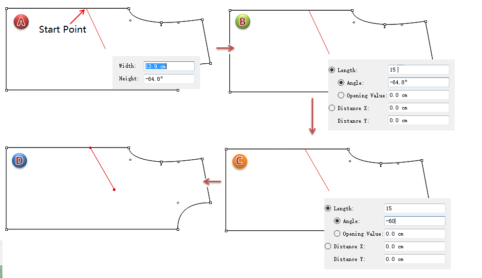
Segment 
For example, draw a segment. If the segment is going to be attached in the piece, activate the piece at first.
Select
Click the start point of the segment, move the cursor, the dialog showing values appears after the cursor
Enter 15 in [Length] item, the rest of the items appears. Enter values in other items, for instance, enter -60 in [Angle] item
Left-click any where or press Enter key to finish operation
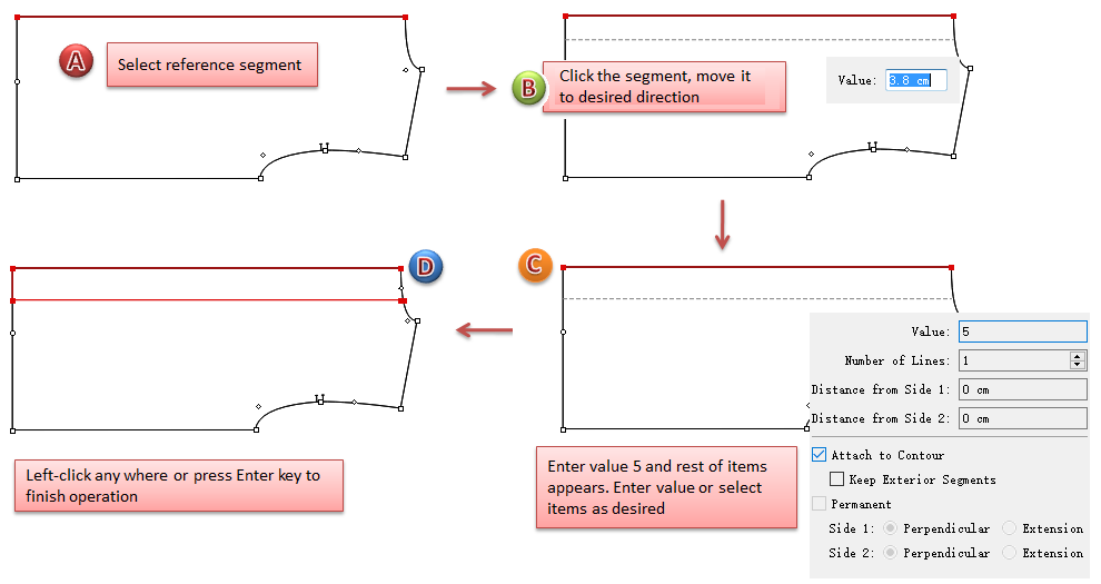
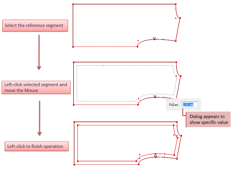
Parallel Line 
Select the desired reference segment (it can be a segment in the same piece or several segments that are connected, or the contour of a closed piece )
Select
Left-click the reference segment
Move the segment to desired direction, a dash line that simulates the parallel line appears, and a dialog box showing values appears after the cursor
Enter specific value (e.g.5cm), then the rest of the items appears, enter value or select item as wish
Left-click any where or press Enter key to finish operation
Ruffle 
Select
Left-click desired position, and the dialog appears after the cursor
Enter desired values (use Tab key to move to next item), or drag the slider to modify the ruffle
Left-click any where or press Enter key to finish operation
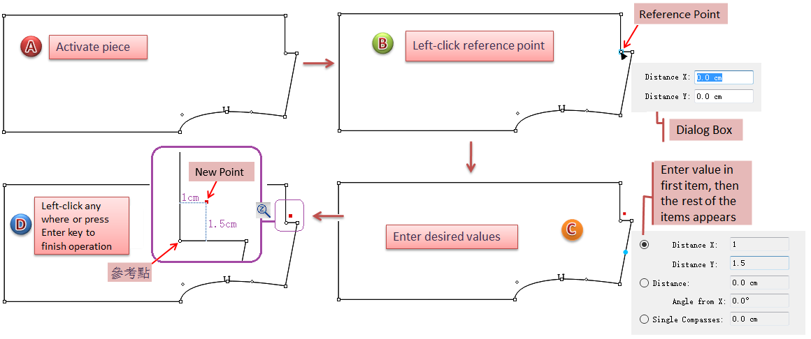
Point 
Activate the piece
Select
Left-click the reference point, the dialog appears after the cursor
Enter desired value, like 1 in [Distance X], then the rest of the items appears. Enter desired values in corresponding items
Left-click any where or press Enter key to finish operation
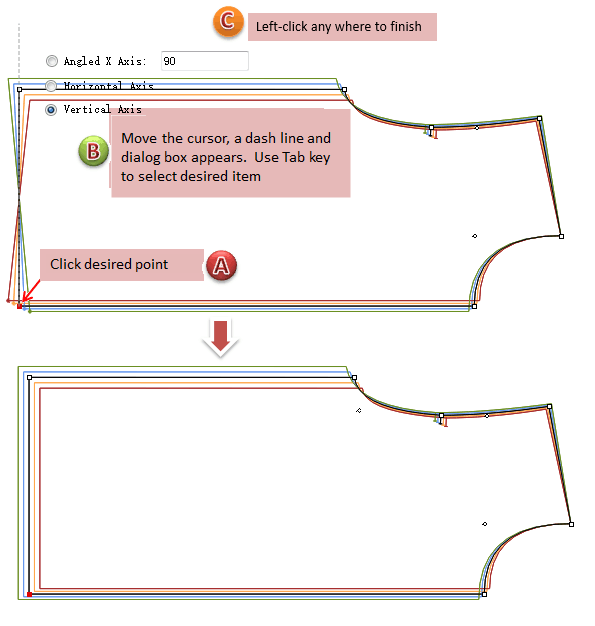
Symmetry Grading 
Activate the piece;
Select
Click the desired point, move the cursor, a dash line appears; meanwhile, a dialog box appears;
Move the dash line (axis) to desired location and left-click to finish modification; or enter desired values (Use Tab key to move to next item), left-click any where to finish modification.
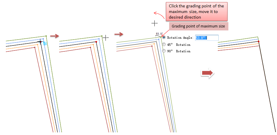
Rotate Grading  
Activate the piece;
Select || tool;
Click the desired point (Medium Size Point), the cursor turns into a cross, meanwhile, the points of other sizes are shown. Move the cross, a dash line appears;
Click the maximum size grading point or the minimum size grading point, move to the desired rotation direction. You can view the rotation angle value and a dialog box appears after the arrow;
Move to desired angle and left-click to finish rotation; or enter angle value (use Tab key to move to next items), then left-click any where to finish operation.
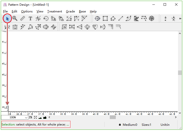
Add operation tips on Info Bar
The operation tips will be displayed on Info Bar when the tools are selected. It helps users to learn the tools easier. When users click the tool icon, the operation description will appear on Info Bar.
For example: Pointer Tool
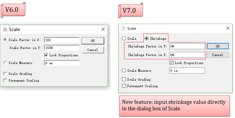
Add Shrinkage in The Dialog Box of Scale
Add Shrinkage in the dialog box of Scale for facilitating users to scale pieces by inputting values.
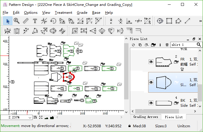
Add Search Function  
Add Search function on the Piece List window, enable users to find the specific piece(s) to operate more easily.
Input the keywords and press the Enter Key to finish accurate or fuzzy search on the Piece List. If the information (piece number, name, description, code or fabric name) of the pieces match the keywords the user entered, the piece(s) will be colored up on the working area.

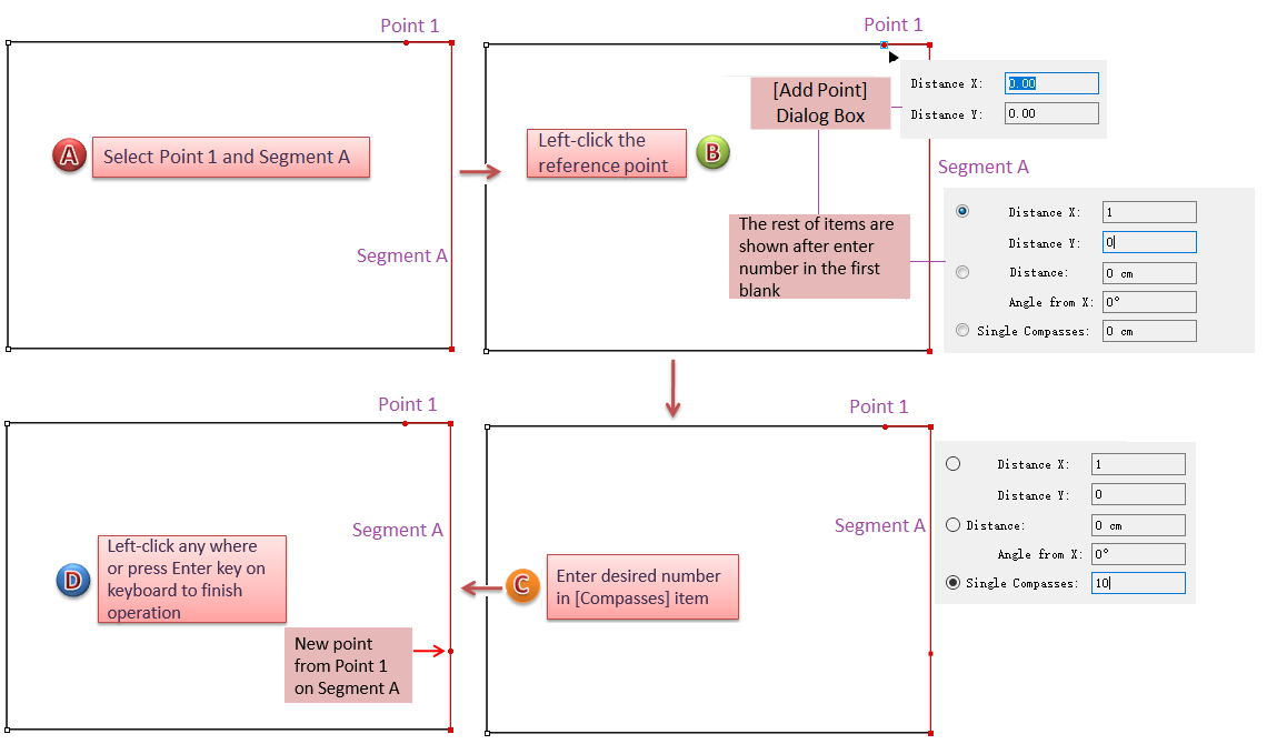
Enhance Add Point Tool 
Single Compasses
Taking a point as reference, users can add a new point on the desired segment with specific length. The distance between that two points is the specific value the user input in Single Compasses dialog box.
For example: now we are going to draw a segment intersects Segment A at the new point Point 2. And the length of the segment (between Point 1 and Point 2) is 15 cm.
How to do:
Select Point 1 and Segment A;
Select
Click Reference Point 1, the dialog box appears lower-right corner of the cursor. Enter value in Distance X, the rest of items are shown;
Enter value 10 in [Compasses] (as the default unit is cm, it works even though enter number without unit)
Left-click any where or press Enter key on your keyboard to finish operation.
Note
For more information about simplifying operation for some tools, please refer to the part of Simplify operation for some tools in this manual.
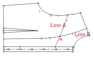
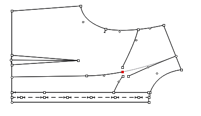
Enhance Attach Segments Tool  
Allow users to break the point on the cross lines (internal lines only). It helps users combine or break point more easily, accelerate the efficiency of making patterns.
How to do:
Activate the desired piece;
Select
Hold down the Shift key, left-click the intersection point;
The following picture shows the result. Use Pointer tool to drag the points to check if they have been broken.
Enhance Ruffle Tool  
Simplify operation, open dialog without using Alt or Option key
Select
Click desired place, dialog box appears following the cursor
Enter number (use Tab key to enter next item), also allows users to modify the ruffle shape by dragging the slider
Left-click any where or press Enter key on keyboard to finish operation
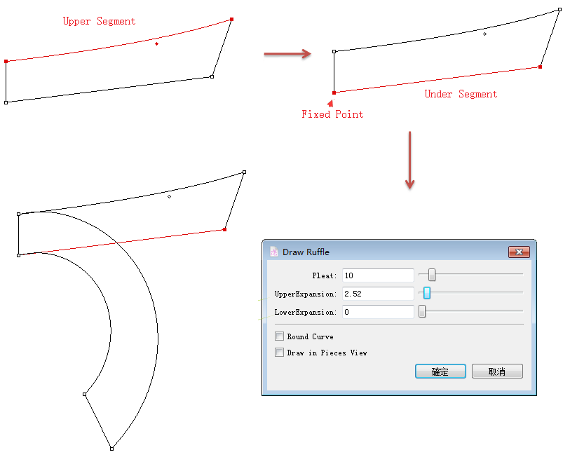
Develop an existing piece(s) into ruffle
For facilitating users to modify pieces, the feature of
How to do:
Activate the piece and select the upper segment;
Select
Right-click anywhere you wish;
Hold down the Ctrl key (Windows) or Command key (Macintosh) and select the under segment;
Right-click anywhere you wish;
Left-click the fixed point, and input the values or drag the slider to modify the ruffle.
Note
For more information about simplifying operation for some tools, please refer to the part of Simplify operation for some tools in this manual.
Enhance Add Point to Segment Tool  
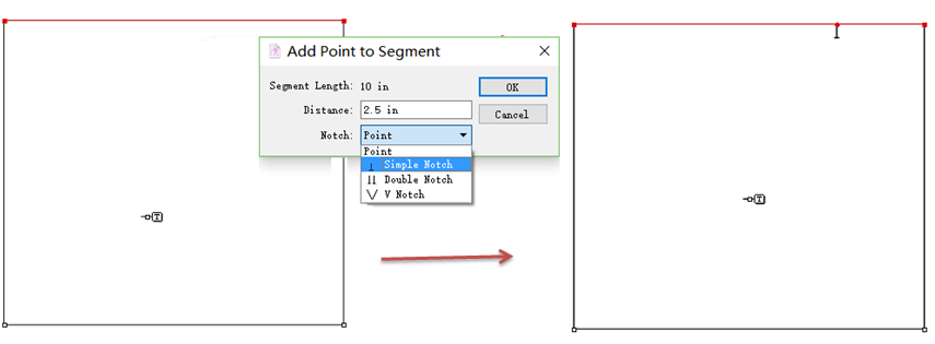
New option: Notch
Notch option is added to the dialog box, users can add a point and a notch at the same time:
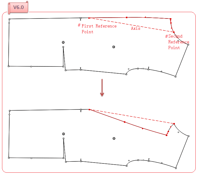
Enhance Symmetry Tool 
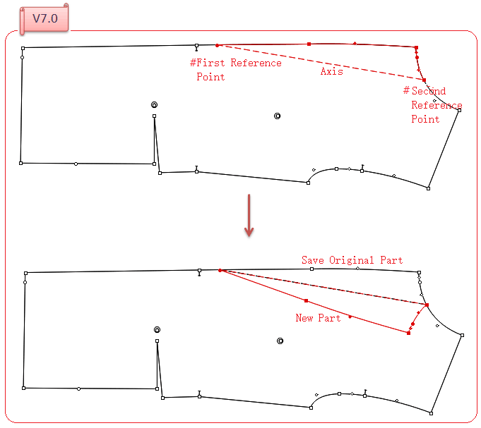
Allow users to create new part with preserving the original one during operating Symmetry.
Create new symmetry shape with saving the original
How to do
Select the element;
Select
Right-click the first reference point and the second one:
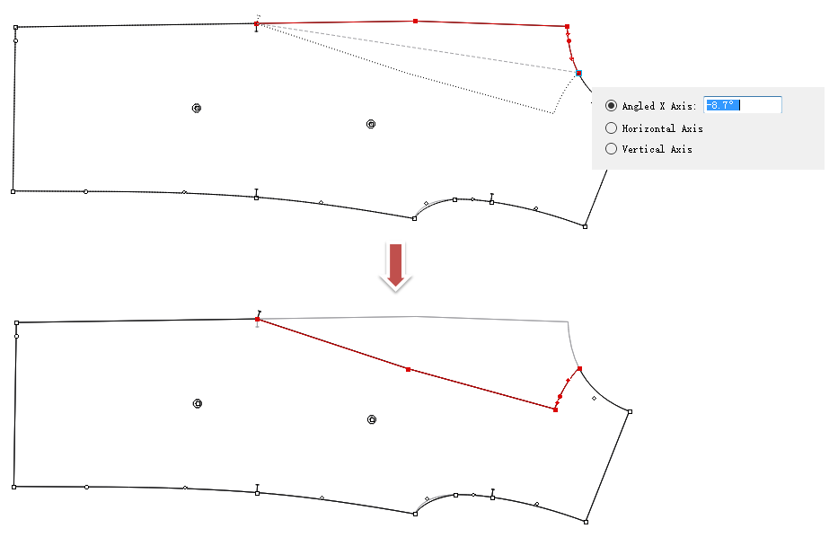
Check values and preview result
Select desired element
Select
Click the first reference point. While moving the cursor, a dash line appears (as an axis), and it previews the result. Meanwhile, specific values can be checked in the dialog box
Click the second reference point
Note
For more information about simplifying operation for some tools, please refer to the part of Simplify operation for some tools in this manual.
Enhance Curve Tool  
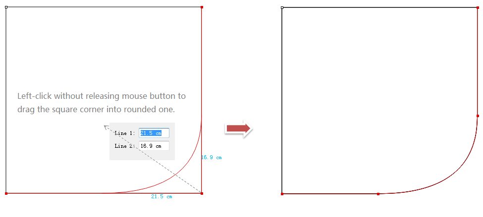
Turn angle into rounded corner by using Curve tool, facilitate users to turn angle into rouned corner quickly and precisely.
Make rounded corner by dragging or inputting precise value
Turn the angle into rounded corner by dragging or entering number directly.
How to do:
Select two desired segments
Select
Left-click to drag the angle point upwards to make rounded corner, during this process, the values are shown. Allow users to enter desired
Left-click any where to finish operation
Note
For more information about simplifying operation for some tools, please refer to the part of Simplify operation for some tools in this manual.
Enhance The Treatment on Seam Corner  
Optimize the feature and add options for treating seam corner, help users make treatment on seam corner more easily.
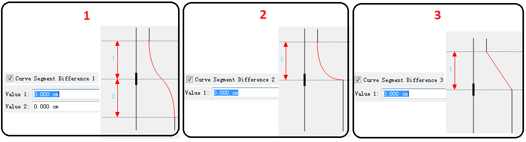
Three new options for treatment on seam corner
Now provide users three new options to choose to treat the seam corner.
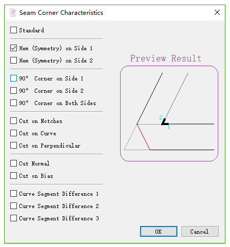
Instant preview for treatment on seam corner
Allow users to preview and check the seam corner. Take Cut Normal as an example:
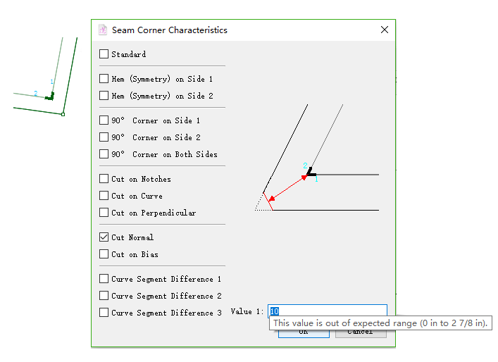
Show maximum value
Now it will show the maximum value of the seam corner to let users know the available range.
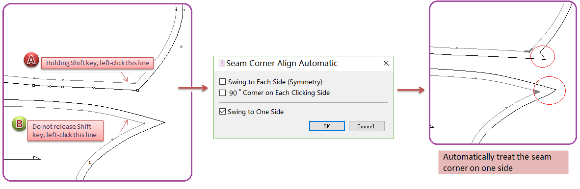
Add Seam Corner Align Automatic
On garment sewing technology, there are technology requirement of swing to each side and swing to one side. So, the seam corner needs to be treated as users’ requirement like swing to each side, swing to one side and aligning seam corner. This new feature is created to help users treat the seam corner more easily and quickly.
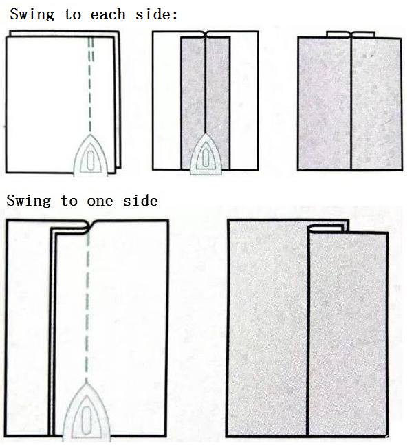
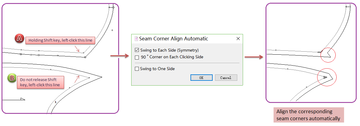
Swing to each side
How to do:
Holding the Shift key, left-click to activate two pieces;
Left-click
Do not release the Shift key, left-click the segment of first desired piece, the cursor becomes a cross, left-click the segment of second piece;
Dialog box appears, select [Swing to One Side] button;
Click OK.
Note
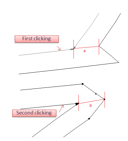
Take the clicking segment as axis and add symmetry seam corner (take the first clicking segment as reference). As the example picture shows, take segment a as reference, the length of segment b is equal to segment a.
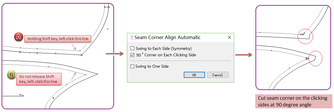
90°corner on each cliking side
How to do:
Holding the Shift key, left-click to activate two pieces;
Left-click
Do not release the Shift key, left-click the segment of first desired piece, the cursor becomes a cross, left-click the segment of second piece;
Dialog box appears, select [90°Corner on Each Cliking Side] button;
Click OK.
Note
Take the clicking segment as axis and add 90 degree seam corner (take the first clicking segment as reference). As the example picture shows, take segment a as reference, the length of segment b is equal to segment a.
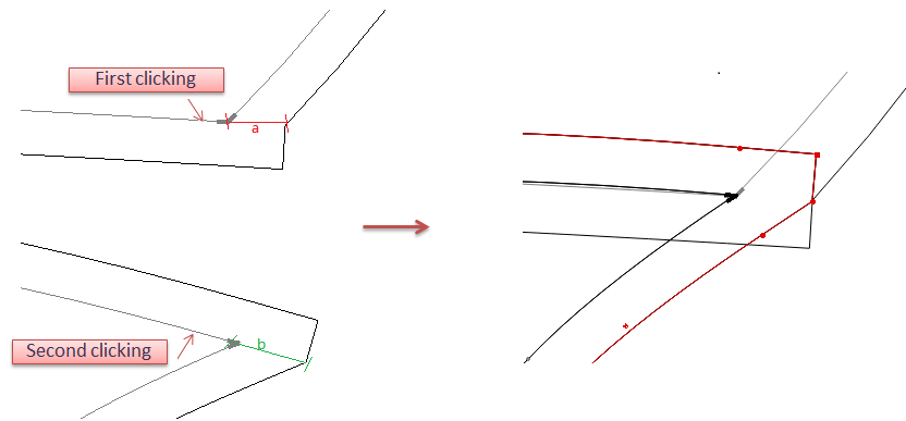
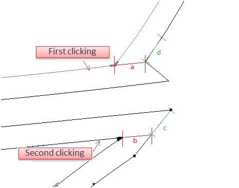
swing to one side
How to do:
Holding the Shift key, left-click to activate two pieces;
Left-click
Do not release the Shift key, left-click the segment of first desired piece, the cursor becomes a cross, left-click the segment of second piece;
Dialog box appears, select [Swing to One Side] button;
Click OK.
Note
Take the first clicking segment as reference. As the example picture shows, the length of segment b is equal to segment a,and segment c is equal to segment d.
Enhance Segment Tool  
Check the values while moving the Mouse
The steps of drawing segment are the same as that of V6.0, but in V7.0, it shows the specific value in the dialog box following the cursor.
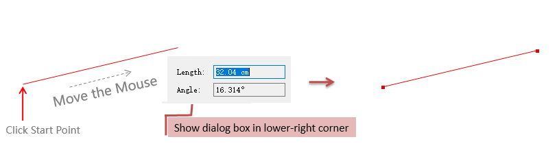
Add Angle item
Allow users to draw a new segment with precise angle between reference point/segment and the new segment.
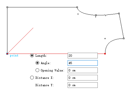
Taking an existing point as reference, draw a new segment with angle between the new segment and X axis:
Select the reference point;
Select
Left-click the corresponding angle point;
The dialog box appears, input the length and angle values you desire (negative value for clockwise angle and positive for counter-clockwise).
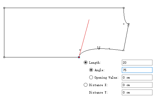
Taking an existing segment as reference, draw a new segment by inputting precise angle and length:
Select the reference segment;
Select
Left-click the angle point;
A dialog box appears, input the precise length and angle values you desire (negative value for clockwise angle and positive for counter-clockwise).
Note
For more information about simplifying operation for some tools, please refer to the part of Simplify operation for some tools in this manual.
Enhance Text Tool  
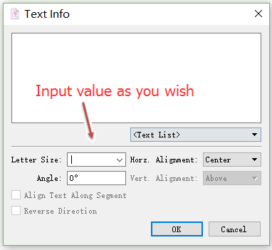
Customize letter size
In addition to select the letter size by pulling down the menu, users can also input the size as wish:
Enhance Parallel Line Tool 
View specific value while moving
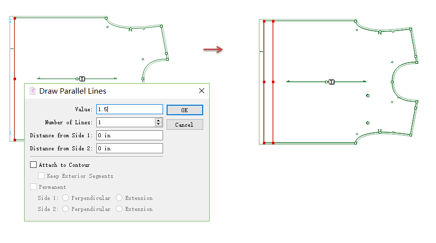
The steps of drawing parallel line are the same as that of V6.0, but in V7.0, the specific values are shown in the dialog box followed the pointer while the pointer is moving.
Add parallel line on the pattern piece with seam allowance
Allow users to create parallel line on the pattern piece with seam allowance.
Note
For more information about simplifying operation for some tools, please refer to the part of Simplify operation for some tools in this manual.
Enhance Join/Split Shapes Tool  
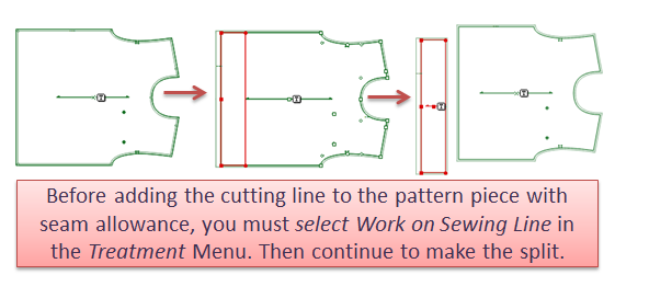
Split the pattern piece with seam allowance
Allow users to split the pattern piece with seam allowance.
Optimize Grading Feature
Facilitate users to grade all sizes by inputting values.
Grading Info
Grading by using Grading Info dialog.
Without specifying any size, input the step value to dX/dY, the system will treat it as the step for larger size by default. Besides, it will recognize the direction and get the step value for the smaller size automatically, and finish grading at once:
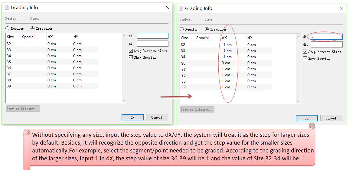
Note
If the user selects a certain size to input value, then other sizes unselected won’t be changed.
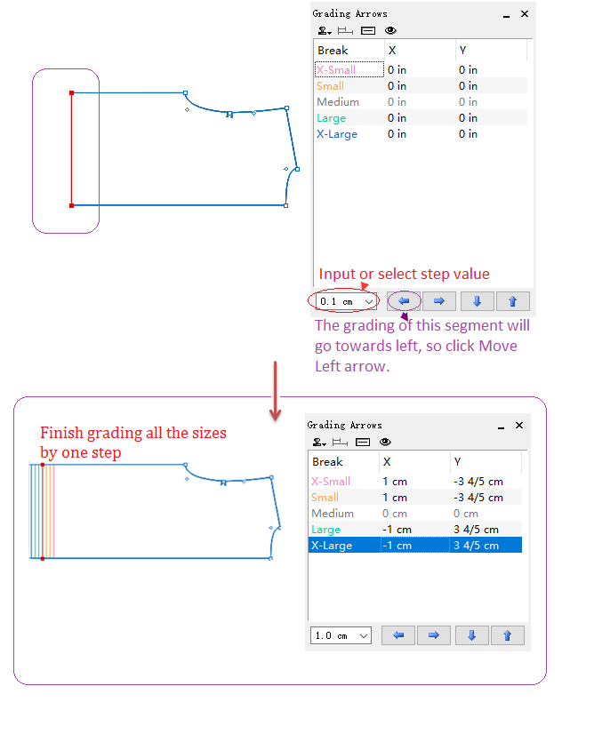
Grading Arrow
Input step value directly:
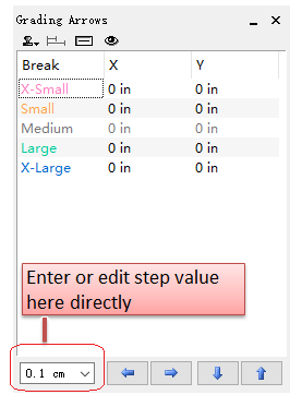
Recognize direction and grade automatically:
It recognizes the direction of the smaller sizes and gets grading automatically according to the direction of the larger sizes:
Select the desired point/segment;
Input or select value to the lower-left corner in the tool frame;
Left-click the arrows to get grading according to the direction of larger sizes.
Show grading of the selected point/segment at once:
Optimize The Feature of Extracting Pieces
The feature of extracting pieces is optimized for users to extract piece(s) more easily and quickly.
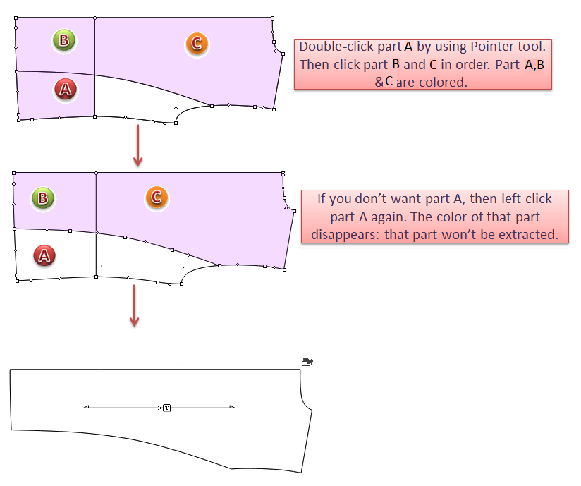
Double-click to extract piece
Double-click to start to extract the part of the piece that users wish. The selected part(s) will be colored. Users can undo the former step.
Select
Pointer tool, double-click the target. The part extracted is colored. Then left-click the desired parts that are divided by lines. Left-click the colored part again to undo. Finish extracting by right-clicking.
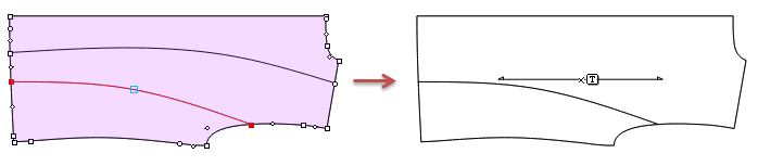
Extract the internal segment if needed while extracting
When you are extracting the part of piece, you can also left-click to select or unselect the internal segment(s) with holding down the Shift key.
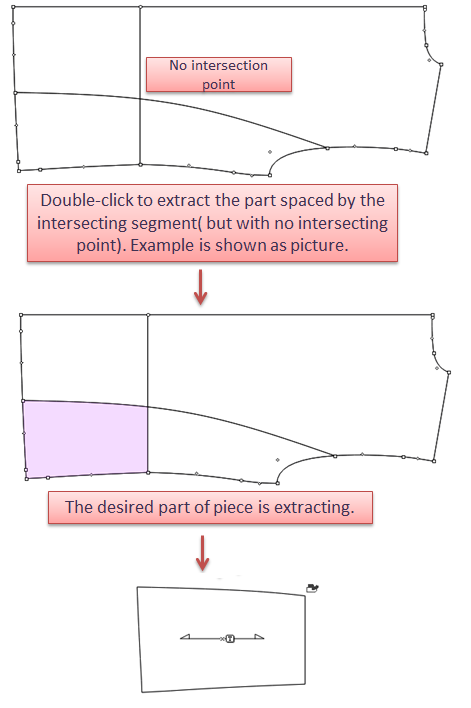
Extract the part of piece even though there is no intersection point on the intersecting lines
In old version of the software, users need to add intersecting point(s) manually so that the desired part(s) can be extracted. Now, in version 7.0, you can extract the part you want directly.
Optimize The Plotter Configuration
Add common plotter
Install Pattern Design, Marker Design and Plot Manager in the same computer.
When one of them adds plotter drive, the rest of them do not need to repeat setting, it will be finished automatically.
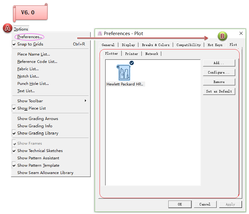
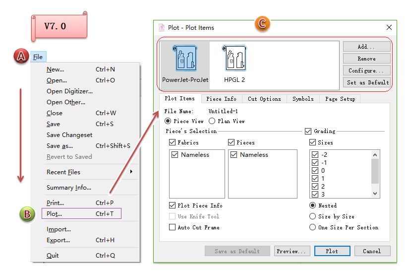
Position adjustment
The plot setting page is moved to path File-Plot. Users can set the plot information and choose to send the file to plot on the same page.
Original position: Option - Preferences - Plot
New postion: File - Plot
Optimize Dart Tool  
Purple marking on corresponding position of the dart
When the user enter the value for creating a dart, the corresponding position of the dart will be highlighted in purple so that the user can recognize any part of the dart easily and quickly.
For example:
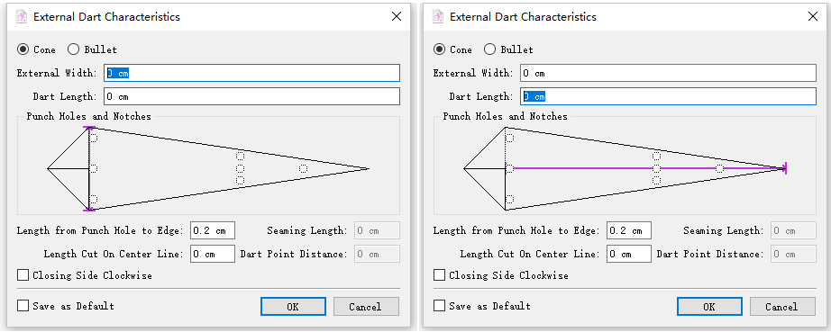
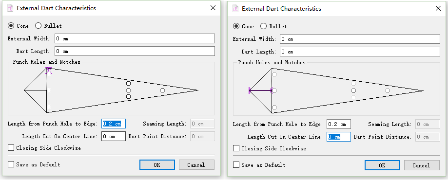
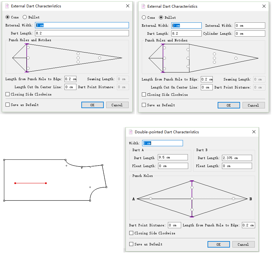
Rearrange the content in dart dialog box
We sort out the darts in the dialog box: Cone, Bullet, Double-pointed Dart, make it more simple to check; the corresponding position of the dart will be highlighted in purple when enter the value.
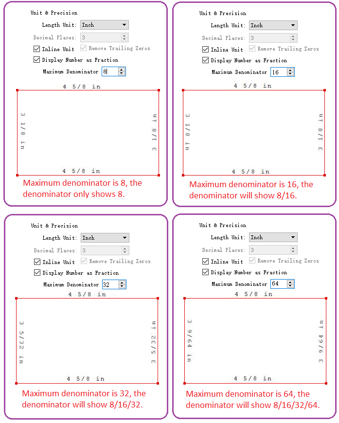
Optimize The Length Unit
When the measurement unit is Inch, the default value will be octal denominator if you select Display Number as Fraction below. The denominator value can be 8/16/32/64.
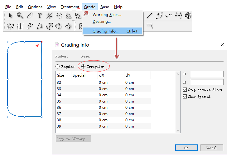
Content Adjustment: Popup of Grading Info
When grade a point or segment that is never graded, click Grade–Grading Info, now it shows Irregular first.
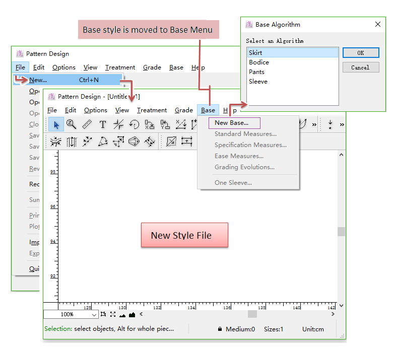
Position Adjustment: Menu
Adjust some item of Menu, make it more handy and clearer.
File - New…
Now click it to open new file directly. The system-provided basic styles will be moved to the pull-down menu of Base.
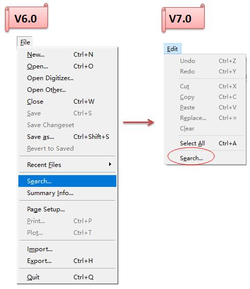
File - Search…
Now it’s moved to the pull down menu of Edit.
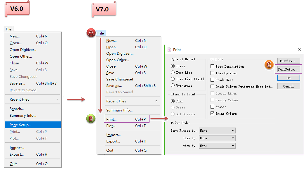
File - PageSetup…
Now PageSetup… is moved to File - Print…:
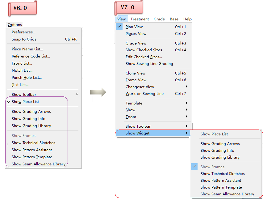
Some Items Involved in Showing Pattern Piece
The pull-down menu Show Piece List, Show Grading Arrows, Show Grading Info…. Show Seam Allowance Library are moved to View - Show Widget.
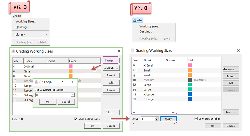
Grading Working Size dialog box
Modify the button Change… in the dialog box of Grading Working Size after clicking the menu Grade - Working Size.
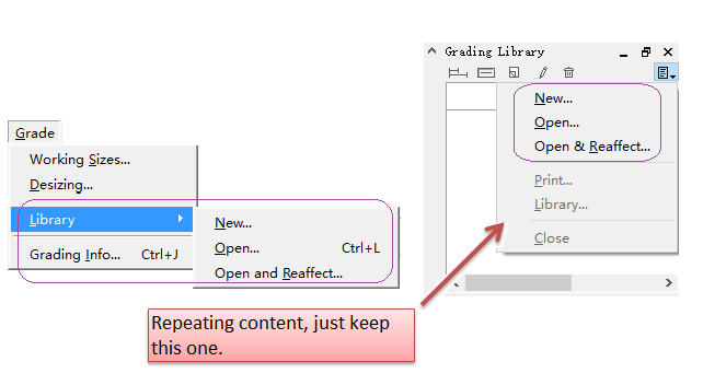
Delete Down-fall menu Library under Grade menu
Delete down-fall menu Library from Grade because it repeated the down-fall menu (New…; Open…; Open & Reaffect…) in the upper right-hand corner of the Grade Library window.
Adjust Import of Other Files Which Are Not .sty
The import methods of other files which is not filename.sty is modified, for example: DXF, Frame Files,Print/Cut Files,and so on.
Adjustment of import method
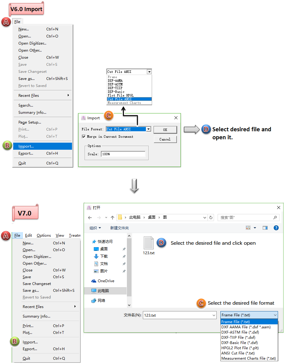
Optimization of importing DXF files
It automatically reads the Inch unit of the imported DXF files, helps users import and open the files easily and quickly.
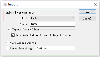
Optimiztion of importing Frame files
Automatically recognize and convert unit. (only for V7.0 Import and V7.0 Import)
E.g.: Pattern staff A made pattern piece and frame in cm, then he exported the frame file and sent it to pattern staff B who applied it on another pattern piece in unit M.
In V6.0, the frame file can’t be used in the files in different unit. Now, in V7.0, the system will automatically recognize the unit and execute contertion.
While importing Frame flie, it automatically recognizes Unicode encoding.
If the encoding of exported file is different from that of the present file, the dialog box Choosing Encoding will appear. Normally the default encoding is the encoding of recent system. If it shows messy codes in the dialog box, click the drop-down menu and selcet the right encoding.
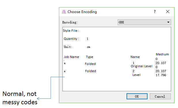
Note
If you don’t know which one is correct, check them one by one till the messy codes disappear.